Inductive Loop Vehicle Detector Gets Modernized

Much like George Lucas and the original Star Wars films, many of us may find that our passion projects are never quite finished, especially when new technology comes around or we just want to make some improvements for their own sake. [Muris] was featured a while back for a vehicle detecting circuit, but is back with some important upgrades to his project. (Which, luckily, do not include any horrible CGI aliens.)

For starters, the entire project has been reworked from the ground up. For anyone unfamiliar with the original project, the circuit detected a vehicle via an inductive loop and was able to perform a task like opening a gate. It now has two independent channels which are polled separately, yet has a reduced parts count which should make construction simpler. The firmware has also been reprogrammed, and in addition to sensing a vehicle’s presence can now also measure the speed of any vehicles passing by.

The complete list of improvements can be found on the project page, and an extensive amount of documentation is available on this if you want to try to roll out your own inductive loop vehicle detector. Of course, this isn’t the only way to detect a vehicle’s presence if inductive loops aren’t really your style.

Continue reading “Inductive Loop Vehicle Detector Gets Modernized”

Inventing The Induction Motor

When you think of who invented the induction motor, Nikola Tesla and Galileo Ferraris should come to mind. Though that could be a case of the squeaky wheel being the one that gets the grease. Those two were the ones who fought it out just when the infrastructure for these motors was being developed. Then again, Tesla played a huge part in inventing much of the technology behind that infrastructure.

Although they claimed to have invented it independently, nothing’s ever invented in a vacuum, and there was an interesting progression of both little guys and giants that came before them; Charles Babbage was surprisingly one of those giants. So let’s start at the beginning, and work our way to Tesla and Ferraris.

Continue reading “Inventing The Induction Motor”

Fail Of The Week: Magnetic Flow Measurement Gone Wrong

Physics gives us the basic tools needed to understand the universe, but turning theory into something useful is how engineers make their living. Pushing on that boundary is the subject of this week’s Fail of the Week, wherein we follow the travails of making a working magnetic flowmeter (YouTube, embedded below).

Theory suggests that measuring fluid flow should be simple. After all, sticking a magnetic paddle wheel into a fluid stream and counting pulses with a reed switch or Hall sensor is pretty straightforward, right? In this case, though, [Grady] of Practical Engineering starts out with a much more complicated flow measurement modality – electromagnetic detection. He does a great job of explaining Faraday’s Law of Induction and how a fluid can be the conductor that moves through a magnetic field and has a measurable current induced in it. The current should be proportional to the velocity of the fluid, so it should be a snap to whip up a homebrew magnetic flowmeter, right? Nope – despite valiant effort, [Grady] was never able to get a usable signal out of the noise in his system. 

The theory is sound, his test rig looks workable, and he’s got some pretty decent instrumentation. So where did [Grady] go wrong? Could he clean up the signal with a better instrumentation amp? What would happen if he changed the process fluid to something more conductive, like salt water? By his own admission, electrical engineering is not his strong suit – he’s a civil engineer by trade. Think you can clean up that signal? Let us know in the comments section. 

Continue reading “Fail Of The Week: Magnetic Flow Measurement Gone Wrong”

What Can We Learn From A Cheap Induction Cooktop?

Sometimes tearing down a cheap appliance is more interesting that tearing down an expensive one. A lot of the best engineering happens when cost is an issue. You may not solve the problem well, but you can solve it well enough for a discount shelf.

[openschemes] purchased a 1.8kW induction hot plate at a low price off Amazon. The reasons for the discount soon became apparent. The worst of which was a fully intolerable amount of high frequency switching noise. Wanting to know how it worked, he took it apart.

After he had it apart on his desk, he deciphered the circuit, and wrote about it clearly. As usual with extremely cheap electronics, some clever hacks were employed. The single micro-controller was used for monitoring, and generated a PWM signal that was instantly converted to DC through some filters. All the switching was done the old fashioned way, which explained why the hotplate seemed so brainless to [openschemes] when he first turned it on.

Lastly, he did some work on manually controlling the cooktop for whatever reason. The good news? He managed to figure out how to control it. Unfortunately he also destroyed his unit in the process, via a misapplication of 1200 volts. A fitting end, and we learned a lot!

Thanks [David Balfour] for the tip!

A Small, 1000W Induction Heater

[Proto G] built a small, desktop induction heater that is capable of making small castings, melting small amounts of metal, and functioning as one of the best solder pots we’ve ever seen.

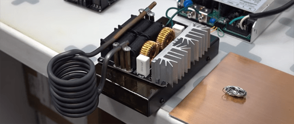
The induction heater is built from a custom Zero Voltage Switching (ZVS) driver and powered by a small 48V, 1000W power supply. While this makes for an exceptionally small induction heater, it’s still very capable. In the video below, it only takes a few seconds to heat a screwdriver up to a temperature that will melt solder.

While an induction heating machine is essentially useless for irons unless you have a few antique, unpowered, blowtorch-powered soldering irons, it does make for a great solder pot. [Proto G] replaced the working coil in his induction heater with litz wire. The actual solder pot is made out of steel conduit wrapped with aerogel-infused fiberglass insulation. Compared to his old solder pot, this machine heats up instantly, and is more than capable of wetting a few wire connections.

The future plan for this inductive heater is to make a few more attachments for different metals, and a [Proto G] has a few aerogel blankets he could use to make some small metal castings.

Continue reading “A Small, 1000W Induction Heater”

3D Printering: Induction Heating

Every filament-based 3D printer you’ll find today heats plastic with resistive heaters – either heater cartridges or big ‘ol power resistors. It’s efficient, but that will only get you so far. Given these heaters can suck down only so many Watts, they can only heat up so fast. That’s a problem, and if you’re trying to make a fast printer, it’s also a limitation.

Instead of dumping 12 or 24 VDC into a resistive heater, induction heaters passes high-frequency AC through a wire that’s inductively coupled to a core. It’s also very efficient, but it’s also very fast. No high-temperature insulation is required, and if it’s designed right, there’s less thermal mass. All great properties for fast heating of plastic.

A few years ago, [SB] over on the RepRap blog designed an induction heater for a Master’s project. The hot end was a normal brass nozzle attached to a mild steel sleeve. A laminated core was attached to the hot end, and an induction coil wrapped around the core. It worked, but there wasn’t any real progress for turning this into a proper nozzle and hot end. It was, after all, just a project.

Finally, after several years, people are squirting plastic out of an induction heated nozzle. [Z], or [Bulent Unalmis], posted a project to the RepRap forums where he is extruding plastic that has been heated with an induction heater. It’s a direct drive system, and mechanically, it’s a simpler system than the fancy hot ends we’re using now.

Electronically, it’s much more complex. While the electronics for a resistive heater are just a beefy power supply and a MOSFET, [Z] is using 160 kHz AC at 30 V. That’s a much more difficult circuit to stuff on a printer controller board.

This could be viewed as just a way of getting around the common 24V limitation of common controller boards; shove more power into a resistor, and it’s going to heat faster. This may not be the answer to hot ends that heat up quicker, but at the very least it’s a very neat project, and something we’d like to see more of.

You can see [Z]’s video demo of his inductive hot end below. Thanks [Matt] for the tip.

Continue reading “3D Printering: Induction Heating”

A Simple LED Flashlight Composed Of A Relay And A Magnet

In our tips line we sometimes receive hacks that are amazing just because of their ingenuity. This relay-powered flashlight is definitely one of them. It has been named RattleGen by its creator [Berto], who apparently often makes simple hacks used in his everyday life (have a look at his YouTube channel).

To understand this hack, you first need to know (in case you didn’t already) that a magnet moving near a conductor (here a coil) induces a voltage at its terminals. This is called electromagnetic induction. In the picture you see above, you may distinguish a disassembled relay with a magnet located on the lever’s end. As a ferromagnetic metal is already placed inside the coil, the lever is by default ‘stuck’ in this position. By continuously pressing the latter on its other end, important voltage spikes are created at the coils terminals. [Berto] therefore used a bridge rectifier to transform the AC into DC, and a 1000uF capacitor to smooth the power sent to his super bright LED. A video of the system in action is embedded after the break.

Continue reading “A Simple LED Flashlight Composed Of A Relay And A Magnet”