Harvesting Electricity From High-Voltage Transmission Lines Using Fences

When you have a bunch of 230 kV transmission lines running over your property, why not use them for some scientific experiments? This is where the [Double M Innovations] YouTube channel comes into play, including a recent video where the idea of harvesting electricity from HV transmission lines using regular fences is put to an initial test.

The nearly final measurement by [Double M Innovations].
The nearly final voltage measurement by [Double M Innovations].
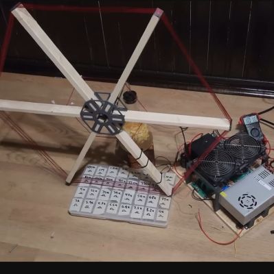
A rather hefty 88 µF, 1200 V capacitor, a full bridge rectifier, and 73 meters (240 feet) of coax cable to a spot underneath the aforementioned HV transmission lines. The cable was then put up at a height consistent with that of fencing at about 1.2 m (4 ft), making sure that no contact with the ground occurred anywhere. One end of the copper shield of the coax was connected to the full bridge rectifier, with the opposite AC side connected to a metal stake driven into the ground. From this the capacitor was being charged.

As for the results, they were rather concerning and flashy, with the 1000 VAC-rated multimeter going out of range on the AC side of the bridge rectifier, and the capacitor slowly charging up to 1000 V before the experiment was stopped.

Based on the capacity of the capacitor and the final measured voltage of 907 VDC, roughly 36.2 Joule would have been collected, giving some idea of the power one could collect from a few kilometers of fencing wire underneath such HV lines, and why you probably want to ground them if energy collecting is not your focus.

As for whether storing the power inductively coupled on fence wire can be legally used is probably something best discussed with your local energy company.

Continue reading “Harvesting Electricity From High-Voltage Transmission Lines Using Fences”

Transformer Inductive Coupling Simulation Is SFW

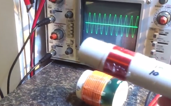
[James] has a friend who teaches at the local community college. When this friend asked him to build a transformer coupling simulation, he was more than happy to oblige. Fortunately for us, he also made a video that explains what is happening while  showing the output on a ‘scope.

For the simulation, [James] built primary and secondary coils using PVC pipe. The primary coil consists of 11 turns of 14AWG stranded wire with 4V running through it applied. The first secondary he demonstrates is similarly built, but has 13 turns. As you’ll see, the first coil induces ~1.5V in the second coil. [James] first couples it with the two windings going the same way, which results in the two 2Mhz waveforms being in phase with each other. When he inserts the secondary the other way, its waveform is out of phase with the primary’s.

His second secondary has the same diameter PVC core, but was wound with ~60 turns of much thinner wire—28AWG bell wire to be exact. This match-up induces 10V on the secondary coil from the 4V he put on the primary. [James]’ demonstration includes a brief Lissajous pattern near the end. If you don’t know enough about those, here’s a good demonstration of the basics coupled with an explanation of the mechanics behind them.

Continue reading “Transformer Inductive Coupling Simulation Is SFW”

Adding LEDs To An Engagement Ring

ring

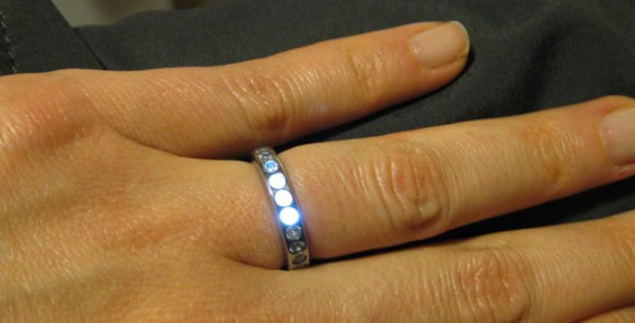
Once upon a time, a nerd met a girl. Things happen as they do, and eventually [Ben] wanted to create the be-all, end-all engagement ring. (here’s a cache) It’s a simple titanium affair with 23 stones around the perimeter. What makes this ring so cool, though, is that it lights up whenever [Ben] and his girl are holding hands.

The metalworking portion of the build was about as easy as you would expect machining titanium to be. After the ring was cut off its bar stock, [Ben] brought it over to a mill where 23 holes for each of the stones were drilled. The stones were affixed to the ring with  jewelers epoxy and the entire ring was buffed to an amazing shine.

The electronics are where this project really shines. Putting a battery of capacitor inside a ring is nigh impossible, so [Ben] decided to power the LEDs with an inductive charging circuit. A coil of wire wound around kapton tape serves as the inductor and a small SMD capacitor powers three very bright and very tiny LEDs.

The inductive charging unit itself is a masterpiece of hackery; [Ben] wanted the ring to light up whenever he and his ladyfriend were holding hands. To do this, [Ben]’s inductive charger is also a wearable device: a large coil of wire is the charger’s transformer and was would to fit around [Ben]’s wrist. The entire charging circuit can be easily hidden under a jacket sleeve, making for a nearly magical light-up ring.

An awesome piece of work, and one of the best jewelry builds we’ve seen in a long time. You can see the inductive coupling and shining LEDs in the video below.

Continue reading “Adding LEDs To An Engagement Ring”

Look Ma, No Wires

[Robotkid249] details how to build a wireless power transmission system. This is similar to the commercial applications we have seen in a TED talk as well is in a Sony prototype. Power is fed to a ring made of magnet wire. A smaller loop is attached to the system that you want to power and picked up from the base unit. In this case, he is powering some LEDs but the concept can be tailored for your purposes such as an inductive charging pad. We’d like to see a hack that incorporates the base into a mouse pad (or the desk itself) and the receiver into the body of a wireless mouse. We’ve seen a commercial solution along these lines but we want one that doesn’t require a physical connection for power transfer.

[Thanks Juan]