ANTIRTOS: No RTOS Needed

Embedded programming is a tricky task that looks straightforward to the uninitiated, but those with a few decades of experience know differently. Getting what you want to work predictably or even fit into the target can be challenging. When you get to a certain level of complexity, breaking code down into multiple tasks can become necessary, and then most of us will reach for a real-time operating system (RTOS), and the real fun begins. [Aleksei Tertychnyi] clearly understands such issues but instead came up with an alternative they call ANTIRTOS.

The idea behind the project is not to use an RTOS at all but to manage tasks deterministically by utilizing multiple queues of function pointers. The work results in an ultra-lightweight task management library targeting embedded platforms, whether Arduino-based or otherwise. It’s pure C++, so it generally doesn’t matter. The emphasis is on rapid interrupt response, which is, we know, critical to a good embedded design. Implemented as a single header file that is less than 350 lines long, it is not hard to understand (provided you know C++ templates!) and easy to extend to add needed features as they arise. A small code base also makes debugging easier. A vital point of the project is the management of delay routines. Instead of a plain delay(), you write a custom version that executes your short execution task queue, so no time is wasted. Of course, you have to plan how the tasks are grouped and scheduled and all the data flow issues, but that’s all the stuff you’d be doing anyway.

The GitHub project page has some clear examples and is the place to grab that header file to try it yourself. When you really need an RTOS, you have a lot of choices, mostly costing money, but here’s our guide to two popular open source projects: FreeRTOS and ChibiOS. Sometimes, an RTOS isn’t enough, so we design our own full OS from scratch — sort of.

The Inner Machinations Of The Arduino Are An Enigma

Arduinos have been the microcontroller platform of choice for nearly two decades now, essentially abstracting away a lot of the setup and lower-level functions of small microcontrollers in favor of sensible IDEs and ease-of-use. This has opened up affordable microcontrollers to people who might not be willing to spend hours or days buried in datasheets, but it has also obscured some of those useful lower-level functions. But if you want to dig into them, they’re still working underneath everything as [Jim] shows us in this last of a series of posts about interrupts.

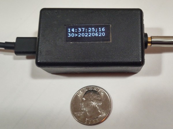
For this how-to, [Jim] is decoding linear timecodes (LTCs) at various speeds. This data is usually transmitted as audio, so the response from the microcontroller needs to be quick. To make sure the data is decoded properly, the first thing to set up is edge detection on the incoming signal. Since this is about using interrupts specifically, a single pin on the Arduino is dedicated to triggering an interrupt on these edges. The rest of the project involves setting up an interrupt service routine, detecting the clock signal, and then doing all of the processing necessary to display the received LTC on a small screen.

The project page goes into great detail about all of this, including all of the math that needs to be done to get it set up correctly. As far as general use of interrupts goes, it’s an excellent primer for using the lower-level functionality of these microcontrollers. And, if you’d like to see the other two projects preceding this one they can be found on the first feature about precision and accuracy, and the second feature about bitbanging the protocol itself.

Diagram of the LTC protocol, showing the difference between 1 bits and 0 bits - both transmitted using one up and one down pulse, but with '1' bit pulses being half as short.

Animate Arcane Protocols With Interrupt-Backed Bitbanging

We often take our “SoftwareSerial” libraries for granted, and don’t investigate what goes on under the hood — until they fail us, at least. Would you like to learn how to harness the power of interrupt-driven bitbanging? [Jim Mack] teaches us how to make our protocol implementations fly using the LTC protocol as a springboard.

LTC (Linear/[Longitudinal] TimeCode) is a widely-used and beautifully-crafted protocol that tends to fly under our radar, and is one that hackers could learn plenty from. It’s used for synchronization of audio/video devices during media production and playback. LTC’s signal is almost digital but not quite: it doesn’t need a clock, and it has no polarity. Additionally, it mimics an audio signal really well, you can decode it at any playback speed, and many other benefits and quirks that [Jim] outlines. You do need to maintain the timings, though, and [Jim]’s article shows us how to keep them right while not inconveniencing your primary tasks.

Continue reading “Animate Arcane Protocols With Interrupt-Backed Bitbanging”

A graph visualising approximation errors - the specific principle pictured is described well by the linked article

Time And Accuracy In Las ATMegas

Do you ever have to ensure that an exact amount of time passes between two tasks in your microcontroller code? Do you know what’s the difference between precision and accuracy? Today, [Jim Mack] tells us about pushing timers and interrupts to their limits when it comes to managing time, while keeping it applicable to an ever-popular ATMega328P target! Every now and then, someone decides to push the frontiers of what’s possible on a given platform, and today’s rules is coding within constraints of an Arduino environment. However, you should check [Jim]’s post out even if you use Arduino as a swearword – purely for all of the theoretical insights laid out, accompanied by hardware-accurate examples!

This will be useful to any hacker looking to implement, say, motor encoder readings, signal frequency calculations, or build a gadget processing or modifying audio in real time. To give you a sample of this article, [Jim] starts by introducing us to distinctions between precision and accuracy, and then presents us with a seemingly simple task – creating exactly 2400 interrupts a second. As much as it might look straightforward, problems quickly arise when clock crystal frequency doesn’t cleanly divide by the sampling frequency that you have to pick for your application! This is just a taste of all the examples of hidden complexity presented, and they’re accompanied with solutions you can use when you eventually encounter one of these examples in your hacker pursuits. In the end, [Jim] concludes with links to other sources you can study if you ever need to dig deeper into this topic.

Keeping our projects true to the passage of time can be an issue, and we’ve been at it for ages – calibrating your RC oscillator is a rite of passage for any ATTiny project. If you ever decide to have an interrupt peripheral help you with timing issues, we’ve gone in-depth on that topic in the past, with a three-part series describing the benefits, the drawbacks and the edgecases of interrupts. Going for a more modern target? Our piece on using interrupts with STM32 is a great path for trying out tools of the modern age.

Bare-Metal STM32: Please Mind The Interrupt Event

Interruptions aren’t just a staple of our daily lives. They’re also crucial for making computer systems work as well as they do, as they allow for a system to immediately respond to an event. While on desktop computers these interrupts are less prominent than back when we still had to manually set the IRQ for a new piece of hardware using toggle switches on an ISA card, IRQs along with DMA (direct memory access) transfers are still what makes a system appear zippy to a user if used properly.

On microcontroller systems like the STM32, interrupts are even more important, as this is what allows an MCU to respond in hard real-time to an (external) event. Especially in something like an industrial process or in a modern car, there are many events that simply cannot be processed whenever the processor gets around to polling a register. Beyond this, interrupts along with interrupt handlers provide for a convenient way to respond to both external and internal events.

In this article we will take a look at what it takes to set up interrupt handlers on GPIO inputs, using a practical example involving a rotary incremental encoder.

Continue reading “Bare-Metal STM32: Please Mind The Interrupt Event”

ESP32 Audio Sampling With Interrupts And IRAM

Interrupting while someone is talking is rude for humans, but smart for computers. [Ivan Voras] shows how to use interrupts to service the ESP32 analog to digital converters when sampling sound. Interestingly, he uses the Arduino IDE mixed with native ESP-IDF APIs to get the best performance.

Like most complex interrupt-driven software, [Ivan’s] code uses a two-stage interrupt strategy. When a timer expires, an interrupt occurs. The handler needs to complete quickly so it does nothing but set a flag. Another routine blocks on the flag and then does the actual work required.

Because the interrupt service routine needs to be fast, it has to be in RAM. [Ivan] uses the IRAM_ATTR attribute to make this work and explains what’s going on when you use it.

…the CPU cores can only execute instructions (and access data) from the embedded RAM, not from the flash storage where the program code and data are normally stored. To get around this, a part of the total 520 KiB of RAM is dedicated as IRAM, a 128 KiB cache used to transparently load code from flash storage.The ESP32 uses separate buses for code and data (“Harvard architecture”) so they are very much handled separately, and that extends to memory properties: IRAM is special, and can only be accessed at 32-bit address boundaries.

This is very important because some ESP-IDF calls — including adc1_get_raw — do not use this attribute and will, therefore, crash if they get pushed out to flash memory. At the end, he muses between the benefit of using an OS with the ESP32 or going bare metal.

If you want to know more about the Arduino on ESP32, we covered that. We also dug deeper into the chip a few times.

Does This Demo Remind You Of Mario Kart? It Should!

Here’s a slick-looking VGA demo written in assembly by [Yianni Kostaris]; it’s VGA output from an otherwise stock ATmega2560 at 16MHz with no external chips involved. If you’re getting some Super Mario Kart vibes from how it looks, there’s a good reason for that. The demo implements a form of the Super Nintendo’s Mode 7 graphics, which allowed for a background to be efficiently texture-mapped, rotated, and scaled for a 3D effect. It was used in racing games (such as Super Mario Kart) but also in many others. A video of the demo is embedded below.

[Yianni] posted the original demo a year earlier, but just recently added detailed technical information on how it was all accomplished. The AVR outputs VGA signals directly, resulting in 100×120 resolution with 256 colors, zipping along at 60 fps. The AVR itself is not modified or overclocked in any way — it runs at an entirely normal 16MHz and spends 93% of its time handling interrupts. Despite sharing details for how this is done, [Yianni] hasn’t released any code, but told us this demo is an offshoot from another project that is still in progress. It’s worth staying tuned because it’s clear [Yianni] knows his stuff.

Continue reading “Does This Demo Remind You Of Mario Kart? It Should!”