Admittedly it’s a bit of a niche application, but if you need lots of flat 3D printed objects, one way to go about it is to print them in a stack and separate them somehow. An old(er) solution is to use a non-extruding “ironing” step between each layer, which makes them easier to pull apart. But another trick is to use the fact that PLA and PETG don’t stick well to each other to your advantage. And thus is born multi-material stack printing. (Video, embedded below the break.)
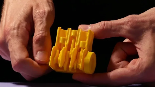
[Jonathan] wants to print out multiples of his fun Multiboard mounting system backplates, and these are the ideal candidate for stack printing: they’re thin, but otherwise take up the entire build plate. As you’d expect, the main trick is to print thin layers of PETG between the PLA plate layers that you do want. He demonstrates that you can then simply pull them apart.
There are some tricks, though. First is to make two pillars in addition to the plates, which apparently convinces the slicer to not flatten all the layers together. (We don’t really understand why, honestly, but we don’t use Bambu slicer for multi-materials.) The other trick that we expect to be more widely applicable, is that [Jonathan] extrudes the PETG interlayers a little thicker than normally. Because the PETG overflows the lower PLA layer, it physically locks on even though it chemically doesn’t. This probably requires some experimentation.
As multi-material printers get cheaper, we’ve seen a lot more innovative uses for them popping up. And we wouldn’t be so stoked about the topic if there weren’t a variety of hacker projects to make it possible. Most recently, the impressive system from [Armored_Turtle] has caught our eye. Who knows what kind of crazy applications we’ll see in the future? Are you doing multi-material yet?
Continue reading “Need Many Thin Parts? Try Multi-material Stack Printing”