It all started when [Damien Walsh] got his hands on some surplus LED boards. Each panel contained 100 mini-PCBs hosting a single bright LED that were meant to be to be snapped apart as needed. [Damien] had a much better idea: leave them in their 20×5 array and design a driver allowing each LED to be controlled over WiFi. He was successful (a brief demo video is embedded down below after the break) and had a few interesting tips to share about the process of making it from scratch.
The first hurdle he ran into was something most of us can relate to; it’s difficult to research something when one doesn’t know the correct terms. In [Damien]’s case, his searches led him to a cornucopia of LED drivers intended to be used for room lighting or backlights. These devices make a large array of smaller LEDs act like a single larger light source, but he wanted to be able to individually address each LED.
Eventually he came across the IS32FL3738 6×8 Dot Matrix LED Driver IC from ISSI which hit all the right bases. Three of these would be enough to control the 100-LED panel; it offered I2C control and even had the ability to synchronize the PWM of the LEDs across multiple chips, so there would be no mismatched flicker between LEDs on different drivers. As for micontroller and WiFi connectivity, we all have our favorites and [Damien] is a big fan of Espressif’s ESP32 series, and used the ESP32-WROOM to head it all up.
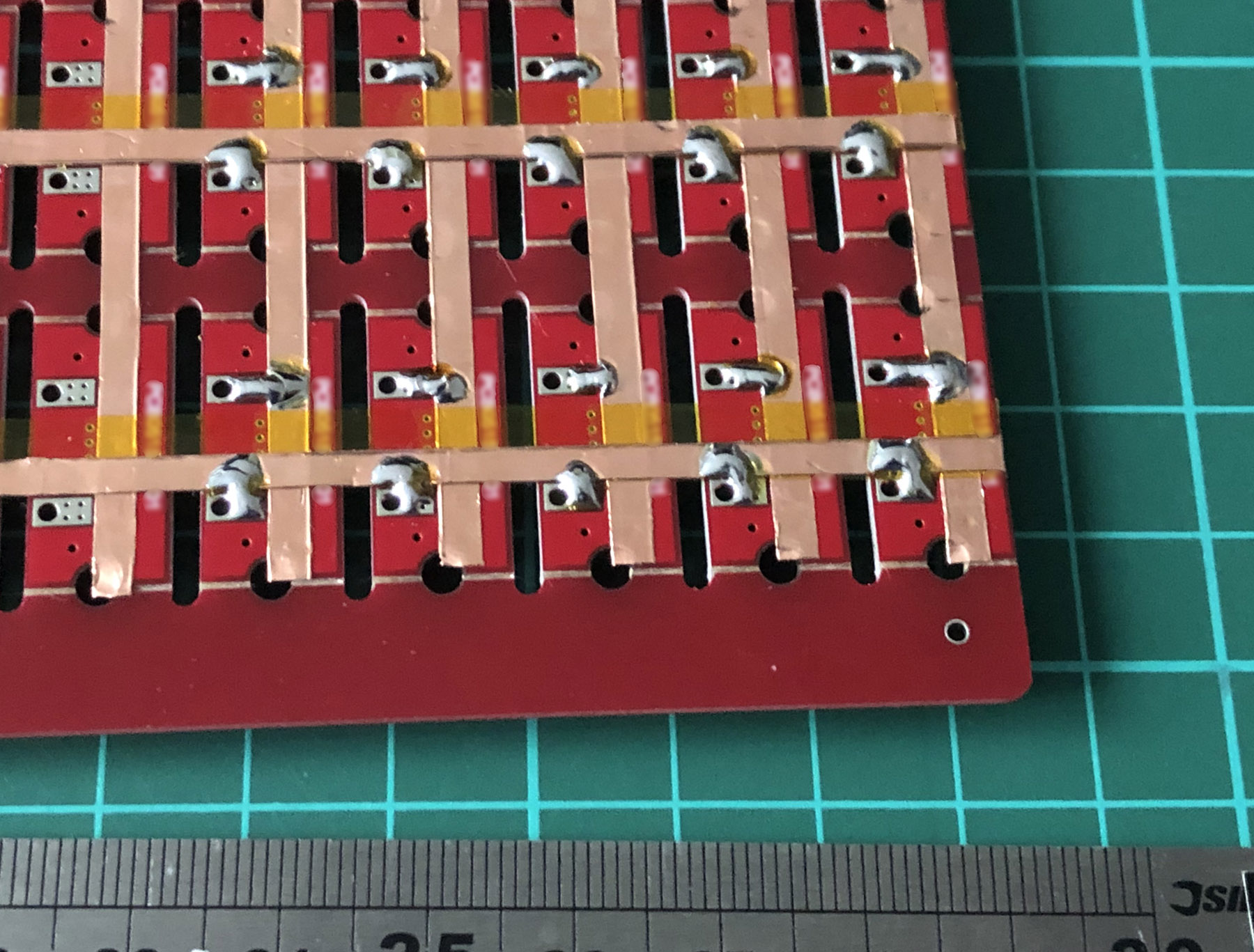
The other issue that needed attention was wiring. Each of the LEDs is on its own little PCB with handy exposed soldering pads, but soldering up 100 LEDs is the kind of job where a little planning goes a long way. [Damien] settled on a clever system of using strips of copper tape, insulated by Kapton (a super handy material with a sadly tragic history.) One tip [Damien] has for soldering to copper tape: make sure to have a fume extractor fan running because it’s a much smokier process than soldering to wires.
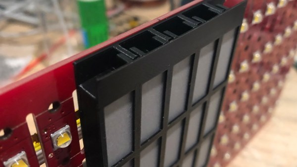
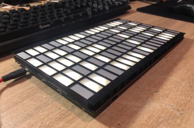
A 3D-printed baffle using tracing paper to diffuse the light rounds out the device, yielding a 20 x 5 matrix of individually-controlled rectangles that light up smoothly and evenly. The end result looks fantastic, and you can see it in action in the short video embedded below.
Continue reading “Rolling Your Own LED Matrix Driver, With Copper Foil Tape To The Rescue”