Over the last couple of years the cyberdeck community has absolutely exploded. Among those who design and build these truly personal computers there are no hard rules, save perhaps making sure the final result looks as unconventional as possible. But one thing that’s remained fairly consistent is the fact that these machines are almost exclusively powered by the Raspberry Pi. Unfortunately, that means they often leave something to be desired in terms of raw performance.
But [MSG] had a different idea. His cyberdeck still has the customary Raspberry Pi inside, but it also has an i7 Intel NUC that can be fired up at the touch of a button. He says it’s the best of both worlds: an energy efficient ARM Linux platform for mobile experimentation, and a powerful x86 Windows box for playing games working from home. It’s the hacker equivalent of business in the front, party in the back.
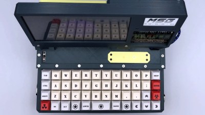 With a KVM connected to the custom Planck 40% mechanical keyboard and seven inch LCD, [MSG] can switch between both systems on the fly. Assuming he’s got the juice anyway; while the Raspberry Pi 4 and LCD is able to run on a pair of 18650 batteries, the cyberdeck needs to be plugged in if he wants to use the power-hungry NUC. If he ditched the Pi he could potentially load up the case with enough batteries to get the Intel box spun up, but that would be getting a little too close to a conventional laptop.
The whole plurality theme doesn’t stop at the computing devices, either. In addition to the primary LCD, there’s also a 2.13 inch e-paper display and a retro-style LED matrix courtesy of a Pimoroni Micro Dot pHAT. With a little Python magic behind the scenes, [MSG] is able to display things like the system temperature, time, and battery percentage even when the LCD is powered down.
In a post on the aptly-named Cyberdeck Cafe, [MSG] talks about how seeing the VirtuScope built by [bootdsc] inspired him to start working towards his own personal deck, and where he hopes to take the idea from here. The unique USB expansion bay behind the screen holds particular promise, and it sounds like a few add-on modules are already in the works. But of course, it wouldn’t be a true cyberdeck if it wasn’t constantly being improved and redesigned. Come to think of it, that makes at least two rules to live by in this community.

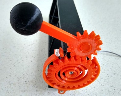 In this case, you’ll be losing all of your nickels to an Arduino Pro Mini. The handle is an upgrade to an earlier slot machine project that uses three 8×8 matrices and a custom driver board. When the spring-loaded handle is pulled, it strikes a micro switch to spins the reels and then snaps back into place. Between each pull, the current score is displayed across the matrix. There’s even a piezo buzzer for victory squawks. We only wish the button under the handle were of the clickier variety, just for the feels. Check out the short demo video after the break.