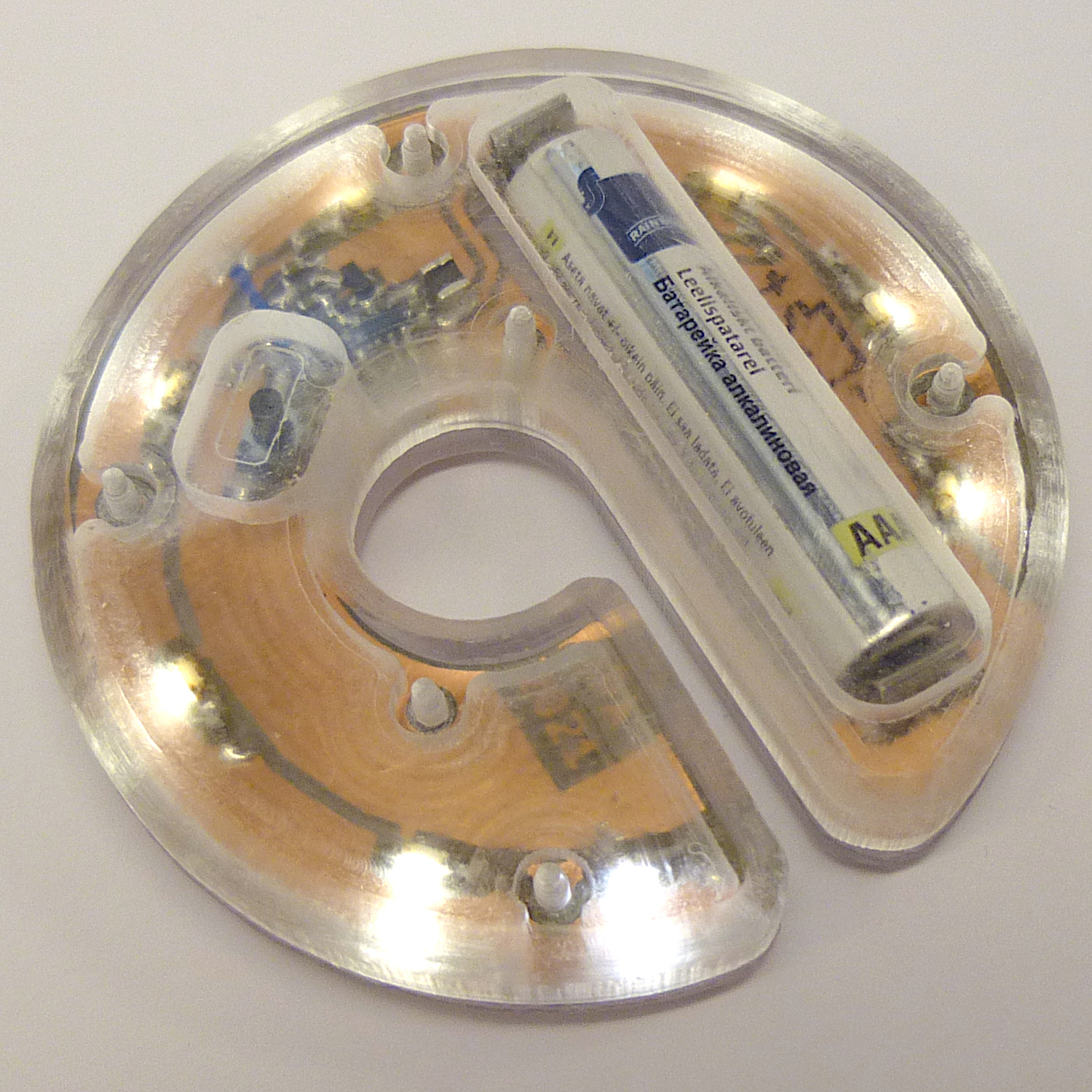
ESP8266 Web Server Saves 60% Power With A 1 Ms Delay

Arduino has a library for quickly and easily setting up a simple web server on an ESP8622-based board, and [Tomaž] found that power consumption on an ESP-01 can be reduced a considerable amount by simply inserting a 1 ms delay in the right place. The reason this works isn’t because of some strange bug or oddball feature — it’s really just a side effect of how the hardware operates under the hood.

[Tomaž] uses the “hello world” example from ESP8266WebServer to explain. In it, the main loop essentially consists of calling server.handleClient() forever. That process checks for incoming HTTP connections, handles them, sends responses, exits — and then does it all over again. A simple web server like this one spends most of its time waiting.

A far more efficient way to handle things would be to launch server.handleClient() only when an incoming network connection calls for it, and put the hardware to sleep whenever that is not happening. However, that level of control just isn’t possible in the context of the Arduino’s ESP8266WebServer library.

So what’s to be done? The next best thing turns out to be a simple delay(1) statement right after each server.handleClient() call in the main loop.

Why does this work? Adding delay(1) actually causes the CPU to spend the vast majority of its time in that one millisecond loop. And counting microseconds turns out to be a far less demanding task, power-wise, than checking for incoming network requests about a hundred thousand times per second. In [Tomaž]’s tests, that one millisecond delay reduced idle power consumption at 3.3 V from roughly 230 mW to around 70 mW — about 60% — while only delaying the web server’s response times by 6-8 milliseconds.

For simple web server applications, this is is for sure a good trick to keep in mind. There are also much more advanced techniques for saving power on ESP8266-based boards; from boards that barely sip a single microamp while sleeping, to coin-cell powered boards that go so far as to modify the TCP/IP stack to help squeeze every bit of power savings possible.

TickTag, a tiny GPS logger with 3d printed case, LiPo battery and a 1 Euro coin for size reference

Tiny GPS Logger For The Internet Of Animals

[Trichl] has created a tiny GPS logger, called ‘TickTag’, designed as an inexpensive location tracking option for animal studies. The low cost, tiny form factor, and large power density of the LiPo battery give it the ability to track large populations of small animals, including dogs and bats.

The TickTag is capable of getting 10,000 GPS fixes from its 30 mAh cell. Each unit is equipped with an L70B-M39 GPS module controlled by an Atmel ATtiny1626 microcontroller and sports a tiny AXE610124 10-pin connection header for programming and communication. GPS data is stored on a 128 kB EEPROM chip with each GPS location fix using 25 bits for latitude, 26 bits for longitude, and 29 bits for a timestamp. Add it all up and you get 10 bytes per GPS data point (25+26+29=80), giving the 10k GPS fix upper bound.

To record higher quality data and extend battery life, the TickTag can be programmed to record GPS location data using variable frequency intervals or when geofencing bounds have been crossed.

Continue reading “Tiny GPS Logger For The Internet Of Animals”

Aluminum Foil 20 Cm Antenna For 10 M Operation

[David], DL1DN, is an Amateur Radio enthusiast with a penchant for low-power (QRP) portable operations. Recently he was out and about, and found that 10 m propagation was wide open. Not discouraged by having forgotten his antenna, he kludges up a makeshift one using a 20 cm length of aluminum foil (see video demonstration below the break). [David] wasn’t completely unprepared, as he did have the loading coil for his portable 20 m antenna, but was missing the telescoping whip. He calculated the whip length should be around 20 cm for 10 m operation, and crinkles up a sheet of foil the approximate length. He tunes it to length by rolling the tip to shorten the “whip” until he gets an SWR minimum.

Schematic of [David]’s QRP Portable Whip Antenna
[David] describes this style of portable antenna in another video, using a more conventional telescoping whip as the radiating element. The loading coil is built from common PVC pipe and insulated wire. While these aren’t necessarily the most efficient antennas, they can do the trick when portability is a major concern. For a different approach, here’s a QRP Hackaday.io portable antenna project using a magnetic loop antenna. But for the ultimate in QRP, check out this transmitter we wrote about in 2013 that uses only voice power to operate.

What are some unusual items you’ve used as makeshift antennas? Let us know in the comments below. Thanks to [mister35mm] for submitting this to our tip line.

Continue reading “Aluminum Foil 20 Cm Antenna For 10 M Operation”

From Nanoamps To Gigahertz: The World’s Most Extreme Op Amps

The operational amplifier, or op amp, is one of the most basic building blocks used in analog circuits. Ever since single-chip op amps were introduced in the 1960s, thousands of different types have been developed, some more successful than others. Ask an experienced analog designer to name a few op amps, and they’ll likely mention the LM324, the TL072, the NE5534, the LM358, and of course the granddaddy of all, the uA741.

If those part numbers don’t mean anything to you, all you need to know is that these are generic components that you can buy anywhere and that will do just fine in the most common applications. You can buy fancier op amps that improve on some spec or another, sometimes by orders of magnitude. But how far can you really push the concept of an operational amplifier? Today we’ll show you some op amps that go way beyond these typical “jellybean” components.

Before we start, let’s define what exactly we mean when we say “operational amplifier”. We’re looking for integrated op amps, meaning a single physical component, that have a differential high-impedance voltage input, a single-ended voltage output, DC coupling, and high gain meant to be used in a feedback configuration. We’re excluding anything made from discrete components, as well as less-general circuits like fixed-gain amplifiers and operational transconductance amplifiers (OTAs).

Continue reading “From Nanoamps To Gigahertz: The World’s Most Extreme Op Amps”

Raspberry Pi Server Cluster In 1U Rack-Mount Case

[Paul Brown] wants to take advantage of off-site server colocation services. But the providers within [Paul]’s region typically place a limit of 1A @ 120V on each server. Rather than search out commercial low-power solutions, [Paul] embraced the hacker spirit and built his own server from five Raspberry Pi 4b single board computers.

The task involves a little bit more than just mounting five Pi4s in a chassis and calling it done. There is an Ethernet switch connecting all the modules to the network, and each Pi has a comparatively bulky SSD drive + enclosure attached. By far the most annoying part of the assembly is the power supply and distribution cabling, which is further complicated by remote controlled power switching relays (one of the computers is dedicated to power management and can shut the other four modules on and off).

Even if you’re not planning on building your own server, check out the thoroughly documented assembly process and parts list — we particularly liked the USB connector to screw terminal breakout connector that he’s using for power distribution. For all the detailed information, assembly instructions and photos, we think a top-level block diagram / interconnection drawing would be very helpful for anyone trying to understand or replicate this project.

There are a lot of connections in this box, and the final result has a messy look-and-feel. But in fairness to [Paul]’s craftsmanship, there aren’t many other ways to hook everything together given the Raspberry Pi form-factor. Maybe a large and costly PCB or using CM4 modules instead of Raspberry Pi boards could help with cable management? In the end, [Paul] reckons he shelled out about $800 for this unit. He compares this expense with some commercial options in his writeup, which shows there are some cheaper and more powerful solutions. But while it may be cheaper to buy, we understand that strong urge to roll your own.

We’ve written about many Pi cluster projects in the past, including this one which contains a whopping 750 Raspberry Pis. Have you ever used a colocation service, and if so, did you use a DIY or an off-the-shelf server?

Astronomical Clock Uses Your Spare Clock Motors

We’ll admit we are suckers for clock projects, and the more unusual, the better. We liked the look of [Peter Balch’s] astronomical clock, especially since it was handcrafted and was a relatively simple mechanism. [Peter] admits that it looks like an astronomical clock, but it isn’t the same as a complex instrument from medieval times. Instead, it uses several standard clock motors modified.

We didn’t quite follow some of the explanations for the rotation of the different elements, but the animated GIF cleared it all up. The inner and outer discs are geared at a 6:5 ratio. It takes 2 hours for the inner disc to make one rotation, meaning that every 12 hours the two discs will be back to where they began relative to one another.

Modifying the motors is fine work, requiring a good bit of disassembly and some glue. The electronics that make it tick are quite interesting. To drive the motors, a very specific pulse train is needed, but you also want to conserve battery as much as possible. A simple oscillator with a hex inverter drew more power than desired and an Arduino, even more so. A PIC12F629, though, could sleep a lot and do the job for a very low current consumption. The final clock should run a year on two AA cells.

Give Your Smart Home A Green Thumb With MQTT

We have all been stuck inside for too long, and maybe that’s why we have recently seen a number of projects attempting to help humans take better care of their housemates from Kingdom Plantae. To survive, plants need nutrients, light, and water. That last one seems tricky to get right; not too dry and not drowning them either, so [rbaron’s] green solder-masked w-parasite wireless soil monitor turns this responsibility over to your existing home automation system.

w-parasite MQTT diagram

Like this low-power soil sensor project and the custom controller for six soil sensors, [rbaron’s] w-parasite uses a “parasitic capacitive” moisture sensor to determine if it’s time to water plants. This means that unlike resistive soil moisture sensors, here the copper traces are protected from corrosion by the solder mask. For those wondering how they work, [rbaron]’s Twitter thread has a great explanation.

The “w” in the name is for WiFi as the built-in ESP-32 module then takes the moisture reading and sends an update wirelessly via MQTT. Depending on the IQ of your smart-home setup, you could log the data, route an alert to a cellphone, light up a smart-bulb, or even switch on an irrigation system.

w-parasite circuit board in a potted plant[rbaron] has shared a string of wireless hacks, controlling the A/C over Slack and a BLE Fitness Tracker that inspired more soldering than jogging. We like how streamlined this solution is, with the sensor, ESP-32 module, and battery all in a compact single board design. Are you asking yourself, “but how is a power-hungry ESP-32 going to last longer than it takes for my geraniums to dry out?” [rbaron] is using deep sleep that only consumes 15uA between very quick 500ms check-ins. The rechargeable LIR2450 Li-Ion coin cell shown here can transmit a reading every half hour for 90 days. If you need something that lasts longer than that, use [rbaron]’s handy spreadsheet to choose larger batteries that last a whole year. Though, let’s hope we don’t have to spend another whole year inside with our plant friends.

We may never know why the weeds in the cracks of city streets do better than our houseplants, but hopefully, we can keep our green roommates alive (slightly longer) with a little digital nudge.