When we used to use firesticks (the pen style plug-in soldering irons) it was always a worry that we might leave them on. But now we use a base unit which has an indicator light to serve as a reminder. Still, [FoxxTexx] isn’t taking any chances and instead built this timer-based outlet which kills the power automatically.
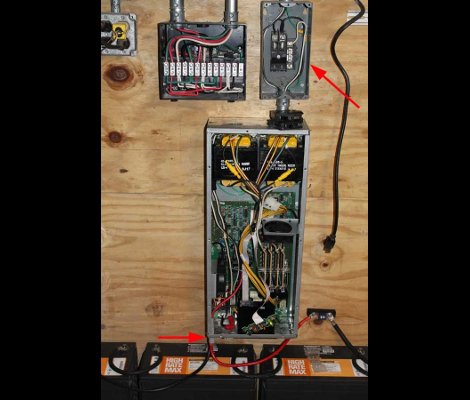
The parts are all pretty common. The timer itself is the same form factor as a light switch and is commonly used for heat lamps or hot tub jets. It feeds the outlet next to it by way of the indicator switches to the right. We like the use of the switches but since mains voltage is still running through them we would suggest using a three-gang box and mounting them on the cover plate so that all the wiring is contained. If done this way you could just have the electrical box siting on your bench, but it is a nice touch to have it mounted this way.
We’ve long been proponents of a timer system. Back when we put together our Hacker’s Soldering Station we just used a plug-in timer unit.