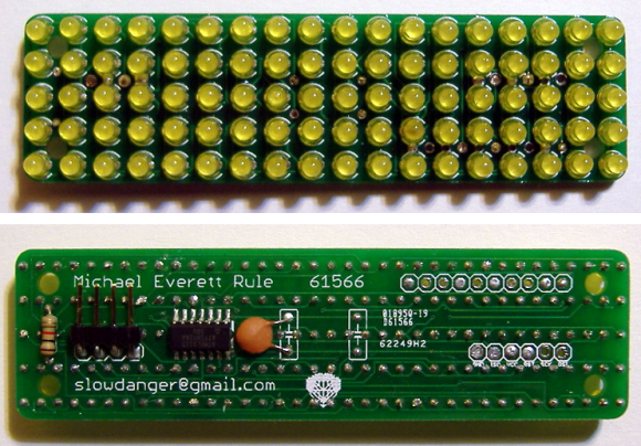
8×8 LED Matrix Pendant Sealed In A Block Of Epoxy

8x8-led-pendant

This is the back side of [Dmitry Grinberg’s] 8×8 LED matrix pendant. He had seen the other projects that used a 5×7 grid but wasn’t really satisfied with the figures that can be drawn in that confined area when each pixel has only the option of being on or off. His offering increases the drawing area and includes the ability to display each pixel at several different levels.

He’s using an ATmega328 microcontroller soldered directly to the pins on the back of the LED module. He mapped out the IO in his firmware to make the soldering as easy as possible. To protect the hardware he fashioned a mold around the edges of the LED package using duct tape. The tape held epoxy in place as it hardened, encasing the microcontroller and holding the power wires and ICSP header tightly.

After the break you can see about six seconds of the device in action. The four levels of brightness for each pixel really do make quite a difference!

Continue reading “8×8 LED Matrix Pendant Sealed In A Block Of Epoxy”

Halloween Props: A Spooky Mirror

This mirror will spook your guests with a variety of static and animated images. It includes a proximity sensor so the images will not appear until someone comes close enough to see themselves in the looking glass.

The electronic parts are quite easy to put together. There is a 32×32 RGB LED matrix mounted on the back of the mirror. It is driven by an IOIO board with some custom firmware written by [Ytai], the creator of that board who happens to live next door to [Alinke]. Where this starts to get interesting is when [Alinke] was working on the mirror to make the LEDs visible from the front. He used a razor knife to put hundreds of scratches in the varnish on the back. This lets just enough light through to see the LEDs, but keeps the mirrored surface reflective. See for yourself in the clip after the break.

The images are fed to the IOIO board by an Android device. We think this could have a lot of use after Halloween as a weather display or news ticker. Perhaps you could even feed it from your diy Android thermostat.

Continue reading “Halloween Props: A Spooky Mirror”

TinyMatrix Derivative Uses PIC Instead Of AVR

[Stu] has a teenage niece whose birthday is coming up and he wanted to give her something unique as a gift. He’s working on an LED matrix pendant that can display pixel graphics, play animations, and scroll messages.

He began the work after drawing inspiration from the TinyMatrix project. That clever design uses a DIP AVR chip soldered directly to the legs of a 5×7 LED matrix. It was powered by a coin cell with the power and ground wires acting as the necklace for the pendant. [Stu] is more comfortable developing using PIC chips, so he based his project on a 16F88. It will not run from a 3V source so he’s got a few issued to work out before the final design is finished.

One thing that’s quite interesting is his side project. After growing weary of hand coding the arrays for each frame of an animation he wrote a GUI in C# that let him design the image and output the code with a few clicks of the mouse.

LED Matrix Pendants

If you want to mess around with some microcontrollers but don’t really have a purpose in mind this project is perfect for you. It’s cheap, easy to assemble, and there’s blinking LEDs! [TigerUp] shows us how he  put together some LED matrix pendants using just five components.

He calls the project Tiny Matrix, which is fitting as the pendant outline is barely 0.5″ by 0.7″. On the back an ATtiny2313 chip has been soldered directly to the legs of the LED display. They just happen to line up with I/O pins on the chip which makes for super simple soldering. Power comes from a coin-cell which is connected to the pendant by a red and black wire which make up the necklace for the device. The last two components not yet mentioned are a momentary push switch for changing modes, and a pull-up resistor on the reset pin. The bill of materials rings in at $4 and his firmware offers up nine different modes as you can see in the clip after the break.

[TigerUp] was inspired by this 8×8 matrix project.

Continue reading “LED Matrix Pendants”

Adding Bluetooth Audio Playback To A Toyota Matrix

In this project [Ryan] shows how he added Bluetooth audio to the stock stereo of his Toyota Matrix. The work he did with his add-on hardware is quite good. And the installation was surprisingly easy. For example, the dashboard bezel which is hanging in the foreground of this picture simply pulls off without the need for any tools. Also, the CD changer input for the stereo is what he uses to patch into the system. It just happened to have a 0.1″ pin header so finding a connector that would work wasn’t a problem.

As for the add-on hardware, he built his own circuit board around an ATmega168 microcontroller and Bluegiga WT32 Bluetooth module. To connect to the car’s data system he went with an RS485 driver chip. It’s not quite the right part but it works well enough for his purposes. So far he can get audio playback working and plans to add support for hands free phone calls and displaying audio track information. Hey, maybe he’ll even add some extra shake-based automation; who knows?

Get a look at the install in the clip after the break.

Continue reading “Adding Bluetooth Audio Playback To A Toyota Matrix”

Bring Your LED Matrix Project Into The Living Room

If you’re able to make a project look this good it shouldn’t be hard to convince that significant other to let you install it in a prominent place in the house. We think [Greg Friedland] pulled this off perfectly by building a 4’x8′ tablet controlled LED matrix.

First of all, everything looks better in a shiny case. It shouldn’t come as a surprise that this looks nice, thanks to the face plates which are mounted in a way that gives them a modern style (we’d expect to see this hanging in Ikea). They’re acrylic diffuser panels meant for used with lighting in a suspended ceiling. They do a nice job of scattering the light put off by the 544 LED modules that make up the display. The wiring was made easy by using LED strands where each pixel has its own control chip (WS2801). It sounds like the display will peak at around 160 Watts, which isn’t really that much considering the area. One nice touch that’s shown off in the video after the break is a full-feature iPad interface that even allows you to paint in light using your finger. But we’re also satisfied that [Greg] posted about the physical build too.

Continue reading “Bring Your LED Matrix Project Into The Living Room”

Power Index Window Display Turns Buildings Into LED Matrices

What started off as a fun project using light bulbs picked up some sponsorship and is going on tour. This project now uses LED modules controlled on the 2.4 GHz band to turn buildings into full color displays. It’s the product of students at Wrocław University of Technology in Poland. The group is something of an extra-curricular club that has been doing this sort of thing for years. But now they’ve picked up some key sponsorships which not only allowed for upgraded hardware, but sent the group on a tour of Universities around Europe. Who would’ve thought you could go on tour with something like this?

Much like the MIT project we looked at in April, this lights up the dark rooms of a grid-like building. It does go well beyond playing Tetris though. The installation sets animations to music, with a custom animation editor so that you can submit your own wares for the next show. Don’t miss the lengthy performance after the break.

Continue reading “Power Index Window Display Turns Buildings Into LED Matrices”