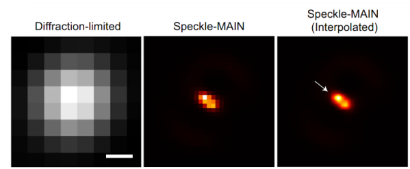
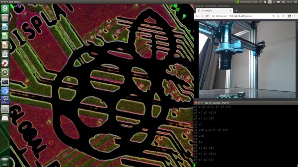
Replacement LED Light Build Uses A Few Tricks

Microscopes have become essential work bench tools for hackers, allowing them to work with tiny SMD parts for PCB assembly and inspection. Couple of years back, mad scientist [smellsofbikes] picked up a stereo microscope from eBay. But its odd-sized, 12 volt Edison-style screw base lamp, connected to a 17 volt AC supply, burned off after a while. He swapped the burnt lamp with the spare, which too blew up after some time. Dumb lamps. Maybe the original spec called for 24 volt lamps, which were unobtanium due to the odd Edison screw base, but those would throw out a pretty yellow-orange glow. Anyhow, for some time, he worked with a jury-rigged goose neck lamp, but frequently moving the microscope and the lamp was becoming a chore. When he got fed up enough about it, he decided to Build a Replacement LED Microscope Light.

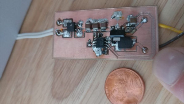
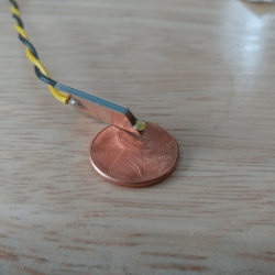
Usually, such builds are plain vanilla and not much to write in about, but [smellsofbikes] has a few tricks worth taking note of. He found a couple of high power, SMD LEDs in his parts bin. They were just slightly wider than 1.6 mm across the terminals. So he took a piece of double sided, copper clad FR4, and edge mounted the LED against one side of the PCB piece, twisting it slightly so he could solder both terminals. This works as a great heat sink for the LED while still having a very narrow profile. This was important as the replacement LED board had to fit the cylinder in which the original lamp was fitted.

The LED is driven by a constant current buck regulator, powered by the original 17 volt transformer. A bridge rectifier and several filter capacitors result in a low ripple DC supply, for which he used the KiCad spice functionality to work out the values. The LM3414 driver he used is a bit off the beaten track. It can run LEDs up to 60 watts at 1 amps and does not require an external current sense resistor. This was overkill since he planned to run the LED at just 150 mA, which would result in a very robust, long lasting solution. He designed the driver PCB in KiCad, and milled it on his LPKF circuit board plotter. The nice thing with CNC milled PCBs is that you can add custom copper floods and extend footprint pads. This trick lets you solder either a 0805 or a 1206 part to the same footprint – depending on what you can dig up from your parts bin.

Continue reading “Replacement LED Light Build Uses A Few Tricks”

This Expedient Microfiche Reader Illuminates Retro Datasheets

You have to be of a certain vintage to remember doing research on microfilm and microfiche. Before the age of mass digitization of public records, periodicals, and other obscure bits of history, dead-tree records were optically condensed onto fine-grain film, either in roll form or as flat sheets, which were later enlarged and displayed on a specialized reader. This greatly reduced the storage space needed for documents, but it ended up being a technological dead-end once the computer age rolled around.

This was the problem [CuriousMarc] recently bumped into — a treasure trove of Hewlett-Packard component information on microfiche, but no reader for the diminutive datasheets. So naturally, he built his own microfiche reader. In a stroke of good luck, he had been gifted a low-cost digital microscope that seemed perfect for the job. The scope, with an HD camera and 5″ LCD screen, was geared more toward reflective than transmissive use, though, so [Marc] had trouble getting a decent picture of the microfiches, even with a white paper backing.

Version 2.0 used a cast-off backlight, harvested from a defunct DVD player screen, as a sort of light box for the stage of the microscope. It was just about the perfect size for the microfiches, and the microscope was able to blow up the tiny characters as well as any dedicated microfiche reader could, at a fraction of the price. Check out the video below for details on the build, as well as what [Marc] learned from the data sheets about his jackpot of HP parts.

With the wealth of data stored on microforms, we’re surprised that we haven’t seen any readers like this before. We have talked about microscopic wartime mail, though.

Continue reading “This Expedient Microfiche Reader Illuminates Retro Datasheets”

Precision Optics Hack Chat With Jeroen Vleggaar Of Huygens Optics

Join us on Wednesday, December 2nd at noon Pacific for the Precision Optics Hack Chat with Jeroen Vleggaar!

We sometimes take for granted one of the foundational elements of our technological world: optics. There are high-quality lenses, mirrors, filters, and other precision optical components in just about everything these days, from the smartphones in our pockets to the cameras that loom over us from every streetlight and doorway. And even in those few devices that don’t incorporate any optical components directly, you can bet that the ability to refract, reflect, collimate, or otherwise manipulate light was key to creating the electronics inside it.

The ability to control light with precision is by no means a new development in our technological history, though. People have been creating high-quality optics for centuries, and the methods used to make optics these days would look very familiar to them. Precision optical surfaces can be constructed by almost anyone with simple hand tools and a good amount of time and patience, and those components can then be used to construct instruments that can explore the universe wither on the micro or macro scale.

Jeroen Vleggaar, know better as Huygens Optics on YouTube, will drop by the Hack Chat to talk about the world of precision optics. If you haven’t seen his videos, you’re missing out!

When not conducting optical experiments such as variable surface mirrors and precision spirit levels, or explaining the Double Slit Experiment, Jeroen consults on optical processes and designs. In this Hack Chat, we’ll talk about how precision optical surfaces are manufactured, what you can do to get started grinding your own lenses and mirrors, and learn a little about how these components are measured and used.

join-hack-chatOur Hack Chats are live community events in the Hackaday.io Hack Chat group messaging. This week we’ll be sitting down on Wednesday, December 2 at 12:00 PM Pacific time. If time zones baffle you as much as us, we have a handy time zone converter.

Click that speech bubble to the right, and you’ll be taken directly to the Hack Chat group on Hackaday.io. You don’t have to wait until Wednesday; join whenever you want and you can see what the community is talking about.

Continue reading “Precision Optics Hack Chat With Jeroen Vleggaar Of Huygens Optics”

Magnifying On The Cheap

If there is one thing we’ve learned during several years of running the Hackaday SMD soldering challenge it is this: Most people need magnification to do good soldering at a tiny scale. The problem is, like most tools, you can buy something as cheap as a $5 binocular headset or you can spend $1,000 or more on a serious microscope. What’s in between? [Noel] looks at some affordable options in a recent video that you can see below.

[Noel] started out with a cheap “helping hand” that has a simple little magnifying glass attached to it. The major criterion was to find something that would have no delay so he could solder under magnification. While it is possible to work under a scope with a little lag in the display, it is frustrating and there are better options.

Continue reading “Magnifying On The Cheap”

Robotics Club Teaches Soldering

Oregon State University must be a pretty good place to go to school if you want to hack on robots. Their robotics club, which looks active and impressive, has a multi-part video series on how to solder surface mount components that is worth watching. [Anthony] is the team lead for their Mars Rover team and he does the job with some pretty standard-looking tools.

The soldering station in use is a sub-$100 Aoyue with both a regular iron and hot air. There’s also a cheap USB microscope that looks like it has a screen, but is covered in blue tape to hold it to an optical microscope. So no exotic tools that you’d need a university affiliation to match.

Continue reading “Robotics Club Teaches Soldering”

Video: Bil Herds Looks At Mitosis

I loved my science courses when I was in Junior High School; we leaned to make batteries, how molecules combine to form the world we see around us, and basically I got a picture of where we stood in the  scheme of things, though Quarks had yet to be discovered at the time.

In talking with my son I found out that there wasn’t much budget for Science learning materials in his school system like we had back in my day, he had done very little practical hands-on experiments that I remember so fondly. One of those experiments was to look and draw the stages of mitosis as seen under a Microscope. This was amazing to me back in the day, and cemented the wonder of seeing cell division into my memory to this day, much like when I saw the shadow of one of Jupiter’s moons with my own eyes!

Now I have to stop and tell you that I am not normal, or at least was not considered to be a typical young’un growing up near a river in rural Indiana in the 60’s. I had my own microscope; it quite simply was my pride and joy. I had gotten it while I was in the first or second grade as a present and I loved the thing. It was just horrible to use in its later years as lens displaced, the focus rack became looser if that was possible, and dirt accumulated on the internal lens; and yet I loved it and still have it to this day! As I write this, I realize that it’s the oldest thing that I own. (that and the book that came with it).

Today we have better tools and they’re pretty easy to come by. I want to encourage you to do some science with them. (Don’t just look at your solder joints!) Check out the video about seeing mitosis of onion cells through the microscope, then join me below for more on the topic!

Continue reading “Video: Bil Herds Looks At Mitosis”

Lego Microscope Does Research

We’ve seen a lot of practical machines built using Lego. Why not? The bricks are cheap and plentiful, so if they can get the job done, who cares if they look like a child’s toy? Apparently, not [Yuksel Temiz]. He’s an engineer for IBM whose job involves taking pictures of microscopic fluidic circuits. When he wasn’t satisfied with the high-power $10,000 microscopes he had, he built his own. Using Lego. How are the pictures? Good enough to appear in many scientific journals.

Clearly, the microscope doesn’t just contain Lego, but it still came in at under $300. According to an interview from Futurism, the target devices are reflective which makes photographing them straight-on difficult. After experimenting with cameras on tripods, [Yuksel] decided he could build his own specialized device. You can see a video of the devices in question and some of the photographs below.

Continue reading “Lego Microscope Does Research”