Thinkpad 13 Gets NVMe Support With Three Jumpers

Hardware restrictions can be unreasonable, and at times, it can be downright puzzling just how arbitrary they are. Such is the case with the Lenovo ThinkPad 13 — it’s got a M.2 M-key socket, yet somehow only supports SATA SSDs in it, despite the CPU being new enough to support both SATA and NVMe effortlessly. [treble] got one of those laptops from a recycler, and decided to figure out just what this laptop’s deal is.

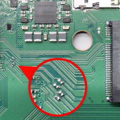
Armed with schematics, she and her friend looked at the M.2 implementation. The slot’s schematic sure looked ready to support either kind of drive, a surprising find. Here’s the catch — Lenovo only populated components for SATA drive support. All you need to switch from SATA to NVMe support is three magnet wire jumpers, or zero-ohm 0402 resistors, and voila; you can now use the significantly cheaper kind of M.2 drives in your ThinkPad.

All is documented, and [treble] even mentions that you could increase the link speed by adding more PCIe lane capacitors that Lenovo, again, left unsoldered. UEFI already has the modules needed to boot from NVMe, too – it’s an outright upgrade for your laptop with just a soldering iron’s touch required, and a reminder that proprietary tech will screw you over for entirely arbitrary reasons. Now, it’s not just laptops you can upgrade with a few resistors — same goes for certain electric cars.

Kali Cyberdeck Looks The Business

Even though we somewhat uncharacteristically don’t have a cyberdeck contest currently underway, there’s never a bad time to get your [Gibson] on. That’s especially true when fate hands you an enclosure as perfect as the one that inspired this very compact Kali Linux cyberdeck.

Now, that’s not to say that we don’t love larger cyberdecks, of course. The ones built into Pelican-style shipping containers are particularly attractive, and it’s hard to argue against their practicality. But when [Hans Jørgen Grimstad], who somehow just sounds like a person who should be building cyberdecks, found a new-old-stock stash of US Army Signal Corps spare parts kits from the 1950s, designation CY-684/GR, he just had to spring into action. After carefully gutting the metal case of the dividers that once protected tubes and other parts, he had some PCB panels made up for the top and bottom. The bottom had enough room for a compact USB keypad, with room left over on the panel for a cooling fan and various connectors. A 7″ HDMI display was added to the panel on the top lid, while a Raspberry Pi 5 with a 500-GB NVMe SSD went below the lower panel. The insides are properly decorated with cyberpunk-esque regalia including a “Self Destruct” button. Sadly, this appears to be unimplemented in the current version, at least for the stated purpose; there’s always hope for version two.

While we love the look and feel of this build and the subtle nods to the cyberpunk aesthetic, it sure seems like you could get some serious work done with a deck like this. Hats off to [Hans] for the build, and here’s hoping he left some of those cool cases for the rest of us.

Continue reading “Kali Cyberdeck Looks The Business”

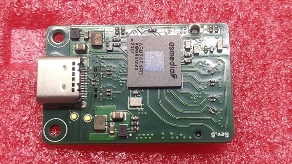
The assembled PCB on red foam, with both a USB-C connector and the ASM2464PD chip visible

Finally Taming Thunderbolt With Third-Party Chips

Thunderbolt has always been a functionally proprietary technology, held secret by Intel until “opening” the standard in a way that evidently wasn’t enough for anyone to meaningfully join in. At least, until last year, when we saw announcements about ASMedia developing two chips for Thunderbolt use. Now, we are starting to see glimmers of open source, letting us tinker with PCIe at prices lower than $100 per endpoint.

In particular, this board from [Picomicro] uses the ASM2464PD — a chipset that supports TB3/4/USB4, and gives you a 4x PCIe link. Harnessing the 40 Gbps power to wire up an NVMe SSD, this board shows us it’s very much possible to design a fully functional ASM2464PD board without the blessing of Intel. With minimal footprint that barely extends beyond the 2230 SSD it’s designed for, curved trace layout, and a CNC-milled case, this board sets a high standard for a DIY Thunderbolt implementation.

The main problem is that this project is not open-source – all we get is pretty pictures and a bit of technical info. Thankfully, we’ve also seen [WifiCable] take up the mantle of making this chip actually hobbyist-available – she’s created a symbol, fit a footprint, and made an example board in KiCad retracing [Picomicro]’s steps in a friendly fashion. The board is currently incomplete because it needs someone to buy an ASM2464PD enclosure on Aliexpress and reverse-engineer the missing circuitry, but if open-source Thunderbolt devices are on your wish list, this is as close as you get today – maybe you’ll be able to make an eGPU adapter, even. In the meantime, if you don’t want to develop hardware but want to take advantage of Thunderbolt, you can build 10 Gbps point-to-point networks.

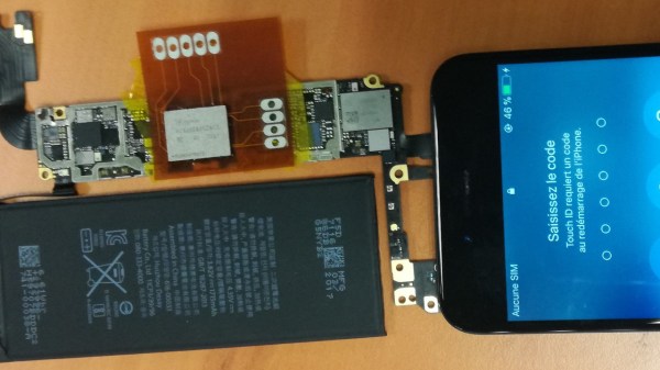
The FPC adapter shown soldered between the BGA chip and the phone's mainboard, with the phone shown to have successfully booted, displaying an unlock prompt on the screen

IPhone 6S NVMe Chip Tapped Using A Flexible PCB

Psst! Hey kid! Want to reverse-engineer some iPhones? Well, did you know that modern iPhones use PCIe, and specifically, NVMe for their storage chips? And if so, have you ever wondered about sniffing those communications? Wonder no more, as this research team shows us how they tapped them with a flexible printed circuit (FPC) BGA interposer on an iPhone 6S, the first iPhone to use NVMe-based storage.

The research was done by [Mohamed Amine Khelif], [Jordane Lorandel], and [Olivier Romain], and it shows us all the nitty-gritty of getting at the NVMe chip — provided you’re comfortable with BGA soldering and perhaps got an X-ray machine handy to check for mistakes. As research progressed, they’ve successfully removed the memory chip dealing with underfill and BGA soldering nuances, and added an 1:1 interposer FR4 board for the first test, that proved to be successful. Then, they made an FPC interposer that also taps into the signal and data pins, soldered the flash chip on top of it, successfully booted the iPhone 6S, and scoped the data lines for us to see.

This is looking like the beginnings of a fun platform for iOS or iPhone hardware reverse-engineering, and we’re waiting for further results with bated breath! This team of researchers in particular is prolific, having already been poking at things like MITM attacks on I2C and PCIe, as well as IoT device and smartphone security research. We haven’t seen any Eagle CAD files for the interposers published, but thankfully, most of the know-how is about the soldering technique, and the paper describes plenty. Want to learn more about these chips? We’ve covered a different hacker taking a stab at reusing them before. Or perhaps, would you like to know NVMe in more depth? If so, we’ve got just the article for you.

We thank [FedX] for sharing this with us on the Hackaday Discord server!

Pineberry Pi HatDrive: Using NVMe SSDs With The Raspberry Pi 5

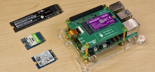
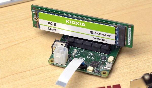
When the Raspberry Pi 5 launched, many were left chomping at the bit after seeing the PCIe FPC connector alongside the promise that an ‘NVMe SSD HAT would be forthcoming’. Although the official Raspberry Pi NVMe HAT is still a long while off, the Polish company Pineberry Pi is ramping up to release its Top & Bottom versions of its very wittily called HatDrive.

They sent a prototype to [Jeff Geerling], who has been putting his grubby mitts all over them before putting together a video showing off the HatDrive Top, which can accept 2230 and 2242 size NVMe drives.

The primary goal of adding an NVMe drive to the RPi is of course to get rid of those slow and fragile SD cards. Although the SD card standard supports near-NVMe-like speeds with UHS-III, the Raspberry Pi 5 bottoms out at UHS-I, around 100 MB/s. Despite this, using an NVMe drive for booting still takes some work, as [Jeff] lays out in a clear article. Most of this involves tweaking the /boot/config.txt file to enable external PCIe support, editing the onboard EEPROM to change the boot order (in lieu of having a PC-like BIOS screen) and getting the OS image flashed onto the NVMe drive you intend to boot from.

Although things seem to work fine during [Jeff]’s testing, some caveats remain, such as the RPi 5 officially supporting only PCIe Gen 2 x1, with Gen 3 possible, but with potential data integrity issues. There’s also the fundamental limit of having only a single lane of PCIe available. If that’s no problem, then Pineberry Pi offers the aforementioned HatDrive Top for traditional HAT-style mounting, and a Bottom version that can accept up to 2280 format NVMe SSDs. Including the provided ribbon cables, you can order the Top and Bottom for €20 and €25.99 respectively, with the first batch to ship in early December.

Continue reading “Pineberry Pi HatDrive: Using NVMe SSDs With The Raspberry Pi 5”

Booting The Raspberry Pi 5 With An NVMe SSD

The Raspberry Pi has come a long way since its humble origins, adding faster processors and better interfaces with each new generation. Now, the Raspberry Pi 5 has a lovely new PCIe port right on board, and [Jeff Geerling] has gone right ahead and slammed in an NVMe SSD as a boot drive.

[Jeff] explains that to use an NVMe to boot, you first have to modify /boot/config.txt to enable PCIe and modify the Raspberry Pi’s boot order. Once the bootloader is appropriately configured, you can boot straight off an SSD with Raspberry Pi OS installed. To get the operating system on to an NVMe drive, he recommends cloning an existing boot volume from a microSD install.

One of the primary reasons you might want to do this is speed. NVMe drives are generally a significant cut above even the best microSD cards, both in speed and reliability. [Jeff] also notes that you can use an NVMe SSD through a PCIe switch on the Pi 5 if you so desire, but you can’t currently boot with this configuration.

It’s a great feature to have on the Pi 5, and it follows on from the earlier implementation on the Raspberry Pi Compute Module 4. Video after the break.

Continue reading “Booting The Raspberry Pi 5 With An NVMe SSD”

M.2 For Hackers – Expand Your Laptop

You’ve seen M.2 cards in modern laptops already. If you’re buying an SSD today, it’s most likely an M.2 one. Many of our laptops contain M.2 WiFi cards, the consumer-oriented WWAN cards now come in M.2, and every now and then we see M.2 cards that defy our expectations. Nowadays, using M.2 is one of the most viable ways for adding new features to your laptop. I have found that the M.2 standard is quite accessible and also very hackable, and I would like to demonstrate that to you.

If you ever searched the Web trying to understand what makes M.2 tick, you might’ve found one of the many confusing articles which just transcribe stuff out of the M.2 specification PDF, and make things look more complicated than they actually are. Let’s instead look at M.2 real-world use. Today, I’ll show you the M.2 devices you will encounter in the wild, and teach you what you need to know to make use of them. In part 2, I will show you how to build your own M.2 cards and card-accepting devices, too!

Well Thought-Out, Mostly

You can genuinely appreciate the M.2 standard once you start looking into it, especially if you have worked with mPCIe devices for some amount of time. mPCIe is what we’ve been using for all these years, and it gradually became a mish-mash of hardly-compatible pinouts. As manufacturers thought up all kinds of devices they could embed, you’d find hacks like mSATA and WWAN coexistence extensions, and the lack of standardization is noticeable in things like mPCIe WWAN modems as soon as you need something like UART or PCM. The M.2 specification, thankfully, accounted for all of these lessons.

Continue reading “M.2 For Hackers – Expand Your Laptop”