Lorenz Attractor Analog Computer With Octave Simulation

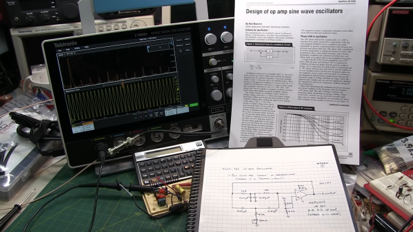
[Janis Alnis] wanted to build an analog computer circuit and bought some multiplier chips. The first attempt used apparently fake chips that were prone to overheating. He was able to get it to work and also walked through some Octave (a system similar to Matlab) simulations for the circuit. You can follow along in the video below.

Getting the little multiplier chips into the breadboard was a bit of a challenge. Of course, there are a variety of ways to solve that problem. The circuit in question is from the always interesting [Glen’s Stuff] website.

From that site:

The Lorenz system, originally discovered by American mathematician and meteorologist, Edward Norton Lorenz, is a system that exhibits continuous-time chaos and is described by three coupled, ordinary differential equations.

So, the circuit is an analog solution to the system of differential equations. Not bad for a handful of chips and some discrete components on a breadboard. We’ve seen a similar circuit on Hackaday.io.

Check out our recent competition winners if you want to see op amps do their thing. Analog computers were a thing. They aren’t always that complicated, either.

Continue reading “Lorenz Attractor Analog Computer With Octave Simulation”

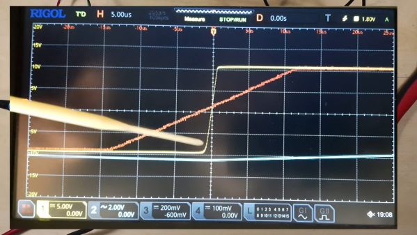
Inside A Fake LM358

[IMSAI Guy] got some fake LM358 op-amps. Uncharacteristically, these chips actually performed well even though they didn’t act like LM358s. [IMSAI Guy] did a video about the fake chips and someone who saw it offered to analyze the part compared to a real LM358 to see what was going on. You can see it too in the video below.

A visual inspection made it obvious that the chip was probably a fake. X-ray analysis was a little less obvious but still showed poor quality and different internals. But the fun was when they actually decapsulated the part.

Continue reading “Inside A Fake LM358”

Inside Electronic Gain Control

Normally, if you want to control the gain of an amplifier, you’ll use a variable resistor. You know, like a volume control. But what if you want to control the amplifier’s gain with a voltage? [Engineering Prof] explains a circuit that can do this using a pair of op amps and a pair of matched JFETs.

The analysis is simple because you assume the op amps are not in saturation, so you can assume that the op amp will do what it needs to do to make the input terminals equal. The left-hand op amp has one input grounded, so the output will drive the first FET  to ensure the negative terminal is also 0V. It is easy to see that the current through R1 must then be the current through the FET, which is going to be the control voltage (which is negative) divided by R1.

Continue reading “Inside Electronic Gain Control”

Quick Negative Voltage For An Op Amp

It is a classic problem when designing with op amps: you need the output to go to zero, but — for most op amps — you can’t quite get down to the supply rail. If your power options are a positive voltage and ground, you can’t get down to zero without a special kind of op amp which might not meet your needs. The best thing to do is provide a negative supply to the chip. Don’t have one? [Peter Demchenko] can help. He uses a simple two-transistor multivibrator along with some diodes and capacitors to generate a minimal negative voltage for this purpose.

The circuit is simple and only produces a small negative voltage. He mentions that into a 910 ohm load, he sees about -0.3V. Not much, but enough to get that op amp down to zero with a reasonable load. Unlike other circuits he’s used in the past, this one is efficient. With a 5-volt input, it draws less than 1.5 mA.

Continue reading “Quick Negative Voltage For An Op Amp”

Listening To Bats As They Search For Food

The range of human hearing goes up to about 20 kilohertz, which is fine for our purposes, but is pretty poor compared to plenty of other animal species. Dogs famously can hear up to about 60 kHz, and dolphins are known to distinguish sounds up to 100 kHz. But for extremely high frequencies we’ll want to take a step into the world of bats. Some use echolocation to locate each other and their food sources, and bats like the pipistrelle can listen in to sounds up to 350 kHz. To listen to them you’ll need a device like the π*pistrelle. (Ed Note: a better explanation is available at the project’s website.)

The original implementation of the bat detector was based on a Raspberry Pi Pico, from which it gets its name. But there have been several improvements on it in the years since it was first developed. The latest can detect bats when it hears their 350 kHz sonar calls thanks to an ultrasonic microphone and op amp. The device then records the bat sounds and then either heterodynes the sound down or time-expands it to human-audible range so the calls can actually be heard. There’s an LED display on the board as well as three input buttons, but an iOS companion app is available to interact with the device as well.

If you want to know for sure which species is flying around at night, you can use machine learning to help figure that out.

Congratulations To Our Op-Amp Challenge Winners!

The real world is analog, and the op-amp is the indispensable building block of many analog circuits. We wanted to give you analog fanatics out there a chance to shine and to encourage our digital brothers and sisters to dip their toes in the murky waters where ones and zeroes define the ends of a spectrum rather than representing the only choice. Hence, we presented the Op Amp Challenge. And you did not disappoint!

We received 83 entries, and it was extraordinarily hard to pick the winners. But since we had three $150 DigiKey shopping sprees to give away, our six judges buckled down and picked their favorites. Whether or not you’ve got the Golden Rules of the ideal op-amp tattooed on your arm, you’ll enjoy looking through all of the projects here. But without further ado…

The Winners

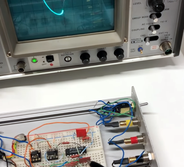
[Craig]’s Op Art is an X-Y voltage generator to plug into an oscilloscope and make classic Lissajous and other spirograph-like images, and it’s all done in analog. Maybe it was his incredible documentation, the nice use of a classic three-op-amp tunable oscillator, or the pun hidden in the title. Whatever the case, it wowed our judges and picked up a deserved place in the top three.

Hearkening back to the pre-digital dinosaur days, [Rainer Glaschick]’s Flexible Analog Computer is a modular analog computer prototyping system on a breadboard backplane. Since you have to re-wire up an analog computer for your particular, it’s great that [Rainer] gave us a bunch of examples on his website as well, including a lunar lander and classic Lorenz attractor demos.

And there was no way that [Chris]’s interactive analog LED wave array wouldn’t place in the top three. It’s a huge 2D analog simulation that runs entirely on op-amps, sensing when your hand moves across any part of its surface and radiating waves out from there. You have to admire the massive scale here, and you simply must check out the video of it in action. Glorious!

Continue reading “Congratulations To Our Op-Amp Challenge Winners!”

Op-Amp Challenge: MOSFETs Make This Discrete Op Amp Tick

When it comes to our analog designs, op-amps tend to be just another jellybean part. We tend to spec whatever does the job, and don’t give much of a thought as to the internals. And while it doesn’t make much sense to roll your own op-amp out of discrete components, that doesn’t mean there isn’t plenty to be learned from doing just that.

While we’re more accustomed to seeing [Mitsuru Yamada]’s digital projects, he’s no stranger to the analog world. In fact, this project is a follow-on to his previous bipolar transistor op-amp, which we featured back in 2021. This design features MOSFETs rather than BJTs, but retains the same basic five-transistor topology as the previous work, with a differential pair input stage, a gain stage, and a buffer stage. Even the construction of the module is similar, using his trademark perfboard and ultra-tidy wiring.

Also new is a flexible evaluation unit for these discrete op-amp modules. This very sturdy-looking circuit provides an easy way to configure the op-amp for testing in inverting, non-inverting, and transimpedance mode, selecting from a range of feedback resistors, and even provides a photodiode input. The video below shows the eval unit in action with the CMOS module, as well as highlights the excellent construction [Mitsuru Yamada] is known for.

Looking for some digital goodness? Check out the PERSEUS-8, a 6502 machine we wish had been a real product back in the day.

Continue reading “Op-Amp Challenge: MOSFETs Make This Discrete Op Amp Tick”