Graphene Optical Boom Emits Light With No Diode

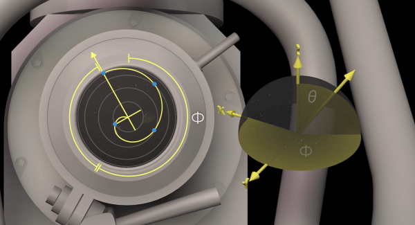
When a supersonic aircraft goes faster than the speed of sound, it produces a shockwave or sonic boom. MIT researchers have found a similar optical effect in graphene that causes an optical boom and could provide a new way to convert electricity into light.

The light emission occurs due to two odd properties of graphene: first, light gets trapped on the surface of graphene, effectively slowing it down. In addition, electrons pass through at very high speeds. Interestingly, the speeds are nearly the same–that is, electrons and trapped light travel at almost the same speed. The researchers found a way to make the electrons move faster than the speed of light (in the graphene) and thus created Cerenkov emissions. Because of the structure of graphene, the resulting light is intense and tightly focused.

The researchers speculate that this technique could be important in building graphene-based optical chips. We’ve talked about mixed graphene and semiconductor chips before. Graphene is pretty exotic stuff. It can even fold itself.

[HomoFaciens] Shows Off With DIY Paper Printer

[HomoFaciens] is always making us feel silly about our purchases. Did we really need to buy a nice set of stepper motors for that automation project? Couldn’t we have just used some epoxy and a threaded rod to make an encoder? Did we need to spend hours reading through the documentation for an industrial inkjet head? Couldn’t we just have asked ourselves, “What would [HomoFaciens] do?” and then made a jailhouse tattoo gun attached to a broken printer carriage and some other household tech trash?

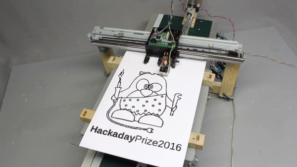
In his continuing work for his Hackaday prize entry, which we have covered before, his latest is a ink (…drop? ) printer. We think the goal is a Gingery book for CNC.  He begins to combine all his previous work into a complete assembly. The video, viewable after the break, starts by explaining the function of a salvaged printer carriage. A motor attached to a belt moves the carriage back and forth; the original linear encoder from the printer is used for positional feedback.

The base of the printer is a homemade y-carriage with another salvaged printer motor and encoder driving a threaded rod. The positional feedback for this axis is provided by a optical mouse gliding on a sheet of graph paper.  The printer nozzle is a cup of ink with a solenoid actuated needle in it. When the needle moves in a hole at the bottom, it dispenses ink.

As always, [HomoFaciens] makes something that is the very definition of a hack. Commenters will have to go elsewhere to leave their favorite debasement.

Continue reading “[HomoFaciens] Shows Off With DIY Paper Printer”

Hackaday Prize Entry: Optical Experiments Using Low Cost Lasercut Parts

Experimenting with optics can be great fun and educational. Trouble is, a lot of optical components are expensive. And other support paraphernalia such as optical benches, breadboards, and rails add to the cost. [Peter Walsh] and his team are working on designing a range of low-cost, easy to build, laser cut optics bench components. These are designed to be built using commonly available materials and tools and can be used as low-cost teaching tools for high-schools, home experimenters and hacker spaces.

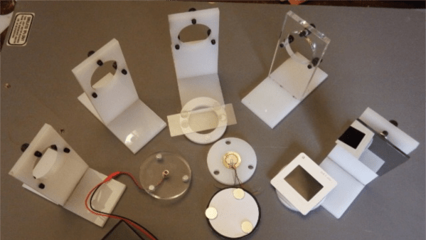
They have designed several types of holders for mounting parts such as lasers, lenses, slits, glass slides, cuvettes and mirrors. The holder parts are cut from ¼ inch acrylic and designed to snap fit together, making assembly easy. The holders consist of two parts. One is a circular disk with three embedded neodymium magnets, which holds the optical part. The other is the base which has three adjustment screws which let you align the optical part. The magnets allow the circular disk to snap on to the screws on the base.

A scope for improvement here would be to use ball plunger screws instead of the regular ones. The point contact between the spherical ball at the end of the screw and the magnet can offer improved alignment. A heavy, solid table with a ferrous surface such as a thick sheet of steel can be used as a bench / breadboard. Laser cut alignment rods, with embedded magnets let you set up the various parts for your experiment. There’s a Wiki where they will be documenting the various experiments that can be performed with this set. And the source files for building the parts are available from the GitHub repository.

Check out the two videos below to see how the system works.

Continue reading “Hackaday Prize Entry: Optical Experiments Using Low Cost Lasercut Parts”

Optical Rectenna Converts Light To DC

Using multiwall carbon nanotubes, researchers at Georgia Institute of Technology have created what they say are the first optical rectennas–antennas with rectifiers that produce DC current. The work could lead to new technology for advanced photodetectors, new ways to convert waste heat to electricity and, possibly, more efficient ways to capture solar energy.

A paper in Nature Nanotechnology describes how light striking the nanotube antennas create a charge that moves through attached rectifiers. Challenges included making the antennas small enough for optical wavelengths, and creating  diodes small enough and fast enough to work at the extremely short wavelengths. The rectifiers switch on and off at petahertz speeds (something the Institute says is a record).  Continue reading “Optical Rectenna Converts Light To DC”

Hacking A Pi Camera With A Nikon Lens

Cell phones have killed many industries. It is getting harder and harder to justify buying an ordinary watch, a calculator, or a day planner because your phone does all those things at least as well as the originals. Cell phones have cameras too, so the days of missing a shot because you don’t have a camera with you are over (although we always wonder where the flood of Bigfoot and UFO pictures are). However, you probably still have a dedicated camera tucked away somewhere because, let’s face it, most cell phone cameras are just not that good.

The Raspberry Pi camera is about on par with a cheap cell phone camera. [Martijn Braam] has a Nikon camera, and he noticed that he could get a Raspberry Pi camera with a C-mount for lenses. He picked up a C to F adapter and proceeded to experiment with Nikon DSLR lenses on the Raspberry Pi camera.

Continue reading “Hacking A Pi Camera With A Nikon Lens”

Disassembled Mouse Keeps Track Of Gas Meter

After building devices that can read his home’s electricity usage, [Dave] set out to build something that could measure the other energy source to his house: his gas line. Rather than tapping into the line and measuring the gas directly, his (much safer) method was to simply monitor the gas meter itself.

The major hurdle that [Dave] had to jump was dealing with an ancient meter with absolutely no modern electronics like some other meters have that make this job a little easier. The meter has “1985” stamped on it which might be the manufacturing date, but for this meter even assuming that it’s that new might be too generous. In any event, the only option was to build something that could physically watch the spinning dial. To accomplish this, [Dave] used the sensor from an optical mouse.

The sensor is surrounded by LEDs which illuminate the dial. When the dial passes a certain point, the sensor alerts an Arduino that one revolution has occurred. Once the Arduino has this information, the rest is a piece of cake. [Dave] used KiCad to design the PCB and also had access to a laser cutter for the enclosure. It’s a great piece of modern technology that helps integrate old analog technology into the modern world. This wasn’t [Dave]’s first energy monitoring system either; be sure to check out his electricity meter that we featured a few years ago.

Wall Wart Computer Mouse

SAMSUNG

This rather bulky looking wall wart is actually a computer mouse. Sure, it may cause your hand to cramp horribly if used for any length of time. But some would say it’s worth that for the hipster value of the thing.

The rather odd shape is somewhat explained by the fact that this was sourced from Ikea. After gutting the transformer found inside the plastic case he had plenty of room to work with. He drilled a hole so that the sensor from a Logitech USB optical mouse can pick up the movement of the mouse. He also got pretty creative when it came to the buttons. The two prongs of the wall plug pivot horizontally to affect the momentary press switches inside.

After the break you can see a quick demo of the project. [Alec] doesn’t consider it to be complete. He wants to make a couple of improvements which include adding weight to make it feel more like the original wall wart, and finding a way to hide the hole he drilled for the sensor.

Continue reading “Wall Wart Computer Mouse”