Automatic Speaker Control Via TV

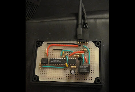
[Jon] wanted his speakers to come on and off along with his TV. The speaker heats up if left on so he didn’t want to do that. But killing the power also resets the volume level (this is an old set of PC speakers and the remote is wired, not IR) so using one of those switched power strips was out as well. He thought a bit about trying to use the power LED on the TV to build his own circuit when it dawned on him. It’s possible to monitor the USB port on the TV and use it to switch on the speakers.

The circuit above uses a couple of opto-isolators to protect both the television and the speakers. The 5V line from the USB port on the back of the TV is monitored by an XNOR gate (which helps to filter out some of the toggling at power-on). When that gate latches it activates a 555 timer which in turn fires up the speakers. Presumable this happens when power is cut as well, but we’ll let you work through the circuit logic yourself.

Remote Shutter Module Uses LCD Screen For Setup

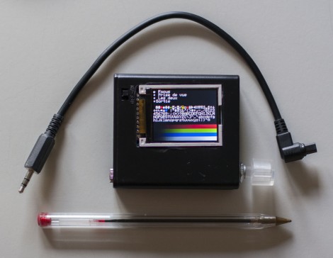
Here’s a full-featured remote shutter project which [Pixel-K] just finished. It seems that he’s interested in taking time-lapse images of the cosmos. Since astrophotography happens outside at night, this presented some special design considerations. He wanted something that he could configure in the dark without zapping his night-vision too much. He also wanted it to be easily configured with a pair of gloves on.

The project enclosure is a 4x AA battery box. He removed the partitions between each cell, leaving plenty of room for the guts. Inside you’ll find a lithium battery and a micro-USB recharger board. It powers the Arduino mini pro which drives the 1.8″ LCD screen and actuates the optoisolator which is responsible for triggering the camera. On the right you can see the clear knob of the clickable rotary encoder. All of the user settings are chosen and selected using just this one knob.

He’s already tried it out on a 6-hour shoot and had no battery life problems or other issues.

24 Cellphone Buttons Controlled With 6 Microcontroller Pins

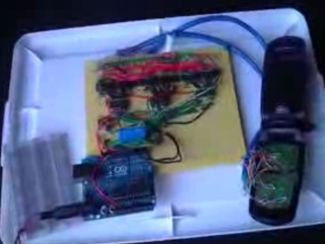
[J8g8j] has been playing around with an old cellphone. He wanted to control it using a microcontroller but since there’s 24 buttons he wasn’t thrilled about hooking up a couple dozen relays to do the switching. Instead, he managed to control all 24-buttons using just 6-pins of a microcontroller.

The proof-of-concept video that he posted on his site shows the phone responding to an arbitrary string of button presses. [J8g8j] spent the majority of his time reverse engineering how the phone’s keypad is wired. Once he figured out the rows and columns of the key matrix he soldered wires to access each of them. This turns out to be 14 connections. To these, he wired up a set of opto-isolators to handle the switching. These are in turn controlled by a set of three 74HC138A 3-8 bit decoders. what’s left are six input pins that leave plenty of room for him to hook up other items to the Arduino serving as the microcontroller.

Christmas Light Controller

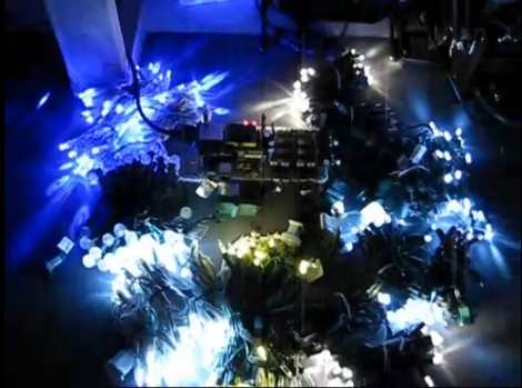
We get a lot of tips about Christmas light controllers but rarely do they contain the kind of juicy detail that [Vince Cappellano] included with his setup. His video explaining the controller he built is embedded after the break and it’s not to be missed.

We think there’s a lot of good design invovled in this porject. First off, he’s got eight physical channels, each with optisolation and a triac for 256 levels of power control. But he was able to double the control to sixteen virtual channels if you’re using LED lighting. That’s because on those strings half of the LEDs are reverse biased compared to the rest. By adding sensing circuitry to the incoming AC, he can switch the triacs to only send positive or negative voltage through the LED strands, which produces the additional virtual channels. And did we mention that he did all this using wire wrapping and point-to-point soldering?

Continue reading “Christmas Light Controller”

Guitar Hero Macro Board

guitarheromacro

Doesn’t look like the Guitar Hero hacks will be slowing up any time soon. In this recent installment, [Thunderhammer3000] built a board to record Guitar Hero “songs”. It is wired inline with with the fret buttons and strum bar and records each of the key presses. Songs can be recorded at slow speed in practice mode and replayed at full speed. The board is Arduino compatible and has two optoisolator chips for collecting the button presses plus a small EEPROM for storage. The board fits easily inside the guitar body.