Dual-Purpose DIY Spot Welder Built With Safety In Mind

Ho-hum, another microwave oven transformer spot welder, right? Nope, not this one — [Kerry Wong]’s entry in the MOT spot welder arms race was built with safety in mind and has value-added features.

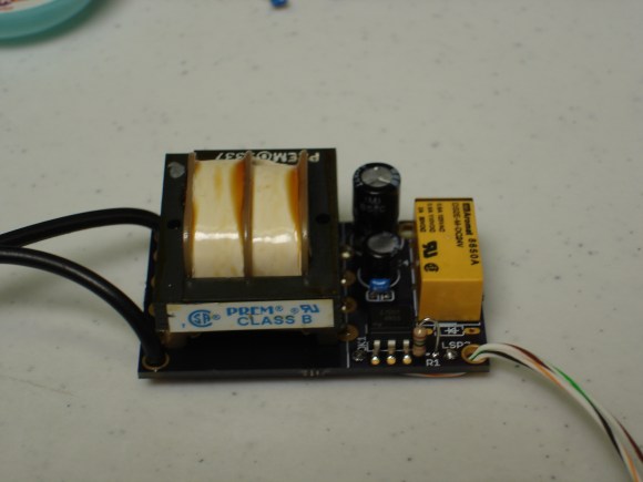
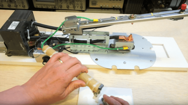
As [Kerry] points out, most MOT spot welder builds use a momentary switch of some sort to power the primary side of the transformer. Given that this means putting mains voltage dangerously close to your finger, [Kerry] chose to distance himself from the angry pixies and switch the primary with a triac. Not only that, he optically coupled the triac’s trigger to a small one-shot timer built around the venerable 555 chip. Pulse duration control results in the ability to weld different materials of varied thickness rather than burning out thin stock and getting weak welds on the thicker stuff. And a nice addition is a separate probe designed specifically for battery tab welding — bring on the 18650s.

Kudos to [Kerry] for building in some safety, but he may want to think about taking off or covering up that ring when working around high current sources. If you’re not quite so safety minded, this spot welder may or may not kill you.

Continue reading “Dual-Purpose DIY Spot Welder Built With Safety In Mind”

Isolated Voltage Measurements Through Frequency

This one’s not a flashy hack, it’s a great piece of work and a good trick to have up your sleeve. Sometimes you’ve got a voltage difference that you’d like to measure, but either the ground potential is at a different level, or the voltages are too high for your lowly microcontroller.

There are tons of tricks with resistive voltage dividers that you can play. But if you want serious electrical isolation from the target, there’s only one way to go — an optocoupler. But optocouplers only really transmit digital signals, and [Giovanni Carrera] needed to measure an analog voltage.

VFC+calibration

Enter the voltage-to-frequency IC that does just what it says: produces a square wave with a frequency that’s proportional to the voltage applied. Pass this square wave through an optocoupler, and you can hit one side with voltages approaching lightning strikes without damaging the microcontroller on the other side. And you’re still able to measure the voltage accurately by measuring the frequency on the digital I/O pins of the microcontroller.

[Giovanni] built up and documented a nice circuit. He even tested it for linearity. If you’re ever in the position of needing to measure a voltage in a non-traditional way, you’ll thank him later.

Transmitting MIDI Signals With XBEE

What do you do when you want to rock out on your keytar without the constraints of cables and wires? You make your own wireless keytar of course! In order to get the job done, [kr1st0f] built a logic translator circuit. This allows him to transmit MIDI signals directly from a MIDI keyboard to a remote system using XBEE.

[kr1st0f] started with a MIDI keyboard that had the old style MIDI interface with a 5 pin DIN connector. Many new keyboards only have a USB interface, and that would have complicated things. The main circuit uses an optoisolator and a logic converter to get the job done. The MIDI signals are converted from the standard 5V logic to 3.3V in order to work with the XBEE.

The XBEE itself also needed to be configured in order for this circuit to work properly. MIDI signals operate at a rate of 31,250 bits per second. The XBEE, on the other hand, works by default at 9,600 bps. [kr1st0f] first had to reconfigure the XBEE to run at the MIDI bit rate. He did this by connecting to the XBEE over a Serial interface and using a series of AT commands. He also had to configure proper ID numbers into the XBEE modules. When all is said and done, his new transmitter circuit can transmit the MIDI signals wirelessly to a receiver circuit which is hooked up to a computer.

PS3 Controller

Get Better At Mortal Kombat By Hacking Your PS3 Controller

Fighting games like Mortal Kombat provide you with a variety of different available moves. These include kicks, punches, grabs, etc. They also normally include various combination moves you can perform. These combo moves require you to press the proper buttons in the correct order and also require you to time the presses correctly. [Egzola] realized that he could just hack his controller to simulate the button presses for him. This bypasses the learning curve and allows him to perform more complicated combinations with just the press of a single button.

[Egzola] started by taking apart his Playstation 3 controller. There were two PCB’s inside connected by a ribbon cable. Luckily, each individual pad for this cable was labeled with the corresponding controller button. This made it extremely simple to hack the controller. [Egzola] soldered his own wires to each of these pads. Each wire is a different color. The wires then go to two different connectors to make them easier to hook up to a bread board.

Each wire is then broken out on the breadboard. The signal from each button is run through a 4n25 optoisolator. From there the signal makes its way back to various Arduino pins. The 4n25 chips keeps the controller circuit isolated from the Arduino’s electrical circuit. The Arduino also has two push buttons connected to it. These buttons are mounted to the PS3 controller.

Now when [Egzola] presses one of the buttons, the Arduino senses the button press and simulates pressing the various controller buttons in a pre-programmed order. The result is a devastating combination move that would normally require practice and repetition to remember. You might say that [Egzola] could have spent his time just learning the moves, but that wasn’t really the point was it? Check out the video below for a demonstration. Continue reading “Get Better At Mortal Kombat By Hacking Your PS3 Controller”

Dual Complementary Optoisolator Logic

You’ve seen CMOS logic, you’ve seen diode-resistor logic, you’ve seen logic based on relays, and some of you who can actually read have heard about rod logic. [Julian] has just invented optoisolator logic. He has proposed two reasons why this hasn’t been done before: either [Julian] is exceedingly clever, or optoisolator logic is a very stupid idea. It might just be the former.

Inside each optoisolator is a LED and a phototransistor. There’s no electrical connection between the two devices, which is exactly what you need in something that’s called an isolator. [Julian] was playing around with some optoisolators one day to create a weird push-pull circuit; the emitter of one phototransistor was connected to the collector of another. Tying the other ends of the phototransistor to +5V and Gnd meant he could switch between VCC and VDD, with every other part of the circuit isolated. This idea whirled around his mind for a few months until he got the idea of connecting even more LEDs to the inputs of the optoisolators. He could then connect the inputs of the isolators to +5V and Gnd because of the voltage drop of four LEDs.

A few more wheels turned in [Julian]’s head, and he decided to connect a switch between the two optoisolators. Connecting the ‘input’ of the circuit to ground made the LED connected to +5V light up. Connecting the input of the circuit to +5 made the LED connected to ground light up. And deeper down the rabbit hole goes [Julian].

With a few more buttons and LEDs, [Julian] created something that is either an AND, NAND, OR NOR, depending on your point of view. He already has an inverter and a few dozen more optoisolators coming from China.

It is theoretically possible to build something that could be called a computer with this, but that would do the unique properties of this circuit a disservice. In addition to a basic “1” and “0” logic state, these gates can also be configured for a tri-state input and output. This is huge; there are only two universal gates when you’re only dealing with 1s and 0s. There are about 20 universal logic gates if you can deal with a two.

It’s not a ternary computer yet (although we have seen those), but it is very cool and most probably not stupid.

Video below.

Continue reading “Dual Complementary Optoisolator Logic”

DIY Optoisolator

MacGyvered Optoisolator Is A Great Introduction

Sometimes the best way to learn about a technology is to just build something yourself. That’s what [Dan] did with his DIY optoisolator. The purpose of an optoisolator is to allow two electrical systems to communicate with each other without being electrically connected. Many times this is done to prevent noise from one circuit from bleeding over into another.

[Dan] built his incredibly simple optoisolator using just a toilet paper tube, some aluminum foil, an LED, and a photo cell. The electrical components are mounted inside of the tube and the ends of the tube are sealed with foil. That’s all there is to it. To test the circuit, he configured an Arduino to send PWM signals to the LED inside the tube at various pulse widths. He then measured the resistance on the other side and graphed the resulting data. The result is a curve that shows the LED affects the sensor pretty drastically at first, but then gets less and less effective as the frequency of the signal increases.

[Dan] then had some more fun with his project by testing it on a simple temperature controller circuit. An Arduino reads a temperature sensor and if the temperature rises above a certain value, it turns on a fan to cool the sensor off again. [Dan] first graphed the sensor data with no fan hooked up. He only used ambient air to cool things down. The resulting graph is a pretty smooth curve. Next he hooked the fan up and tried again. This time the graph went all kinds of crazy. Every time the fan turned on, it created a bunch of electrical noise that prevented the Arduino from getting an accurate analog reading of the temperature sensor.

The third test was to remove the motor circuit and move it to its own bread board. The only thing connecting the Arduino circuit to the fan was a wire for the PWM signal and also a common ground. This smoothed out the graph but it was still a bit… lumpy. The final test was to isolate the fan circuit from the temperature sensor and see if it helped the situation. [Dan] hooked up his optoisolator and tried again. This time the graph was nice and smooth, just like the original graph.

While this technology is certainly not new or exciting, it’s always great to see someone learning by doing. What’s more is [Dan] has made all of his schematics and code readily available so others can try the same experiment and learn it for themselves.

24V Relay Driver Circuit

driving-24v-relays

[Glitch] got his hands on a slew of relays which are meant for use in industrial equipment. They are designed to operate at 24V. He wanted to use these with common microcontrollers and instead of buying a driver he designed and built his own.

There’s a few things to consider with a project like this. You need a power source, a way to level convert the driver pins, and some protection in case something goes wrong with the circuit. Looking at the board above should give you some idea of what’s going on. There’s a big transformer taking up half of the footprint. This steps down mains voltage to something a 7824 regulator can handle. That’s a 24V linear regulator which is fed by a bridge rectifier along with some smoothing capacitors. With the source taken care of [Glitch] uses an optoisolator for both protection and level conversion. After working the bugs out of the design he was able to control the relay using 3.3V, 5V, or 12V.