Most hackers are rankled by those “Warranty Void If Broken” seals on the sides of new test equipment. Even if they’re illegal, they at least put the thought in your head that the space inside your new gear is off-limits, and that prevents you from taking a look at what’s inside. Simply unacceptable.
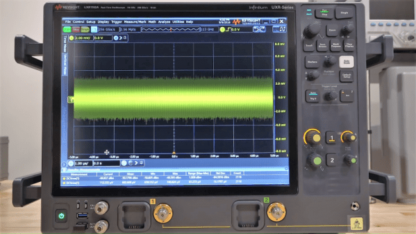
[Shahriar] has no fear of such labels and tears into just about everything that comes across his bench. Including, most recently, a $1.3 million 110-GHz oscilloscope from Keysight. It’s a teardown that few of us will ever get the chance to do, and fewer still would be brave enough to attempt. Thankfully he does, and the teardown video below shows off the remarkable engineering that went into this monster.
The numbers boggle the mind. Apart from the raw bandwidth, this is a four-channel scope (althought the unit [Shahriar] tested is a two-channel) that doesn’t split its bandwidth across channels. The sampling rate is 256 GS/s and the architecture is 10-bits, so this thing is dealing with 10 terabits per second. We found the extra thick PCBs, which are perhaps 32-layer boards, to be especially interesting, and [Shariar]’s tour of the front end was fascinating.
It all sounds like black magic at first, but he really makes the technology approachable, and his appreciation for fine engineering is obvious. If you’ve got even a passing interest in RF electronics you should check it out. You might want to brush up on microwave topics first, though; this Doppler radar teardown might help.
Continue reading “Tearing Into A $1.3 Million Oscilloscope” →