Giving A 4k Webcam Special Eyes

It’s a problem as old as photography: your camera is only as good as your lens. As cameras shrink, so do lenses, and so do the options for upgrading to a better lens. And forget about switching to a different focal length or aperture — it’s often just not an option. Unless you make it an option by adding a CS lens mount to a high-end webcam.

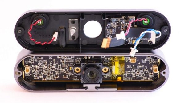
We’ll stipulate that at 4k resolution and packed with all sorts of goodies, the Logitech Brio Pro is a heck of a nice camera. And the lens isn’t bad either, as you’d hope for a camera with almost 9 megapixels at its disposal. But with an optical field of view optimized for video conferencing, it’s hard to use this premium camera for much else. [Saulius] fixed that by taking the camera apart and adding a new case with a built-in C- and CS-mount, resulting in literally thousands of lens choices. [Saulius]’ post has valuable teardown information, which includes exposing the CCD sensor completely. The new case is sold as a kit, but it looks like a 3D-printed case would be pretty easy to whip up.

[Salius] sure seems to love those optical hacks, whether they be a budget microscope camera, high-resolution LIDAR, or capturing license plates at great distances.

EMMC Hacks For The Speed And Capacity Upgrade Win

You could say that it is the essence of a site like this one, that the kind of people who form our readership are also the kind of people who examine the specs of the devices in front of them to reveal hidden features. Such was the case with [Ryan], who noticed that the eMMC controller on his 96Boards HiKey development board supports both HS200 data transfer speeds and 1.8v signaling, both of which it wasn’t using.

In unlocking the extra performance, he takes readers through a primer on the device tree, and is happy to report that his transfer rate has increased from 26 to 36 MB/s, a tidy return on his work.

However, the story doesn’t end there. The 8GB Samsung eMMC chip wasn’t quite as roomy as he’d have liked, so it was time to replace it with a 32GB version. Even with careful desoldering, he managed to lift a few pads, though very fortunately they were ones that were either NC or power rails that were duplicated elsewhere. Some tricky reflowing of what is quite a formidable BGA package to do by hand, and he was rewarded with a working board featuring higher flash capacity. We salute him for taking it on, we probably wouldn’t have had the courage.

We’ve brought you a similar upgrade before, this time an eMMC on a Nexus 5 phone.

Thanks [darkspr1te] for the tip.

Playing Mario On An Oscilliscope

Any display can be connected to a microcontroller and used as a display if you know the protocol to use and have enough power in your micro. Sometimes, an odd display is used just “because it’s there.” This seems to be the case for Reddit user [phckopper], who has used a STM32 and a PS2 joystick to play a version of a Mario game on an oscilloscope.

There’s not many technical details but [phckopper] lets us know that the rendering is done using the SPI on the STM, transferred via DMA, which is synchronized to two saw-tooth waves that are fed in to the X and Y axes of the oscilloscope.  The Z axis, which controls the brightness of the dot, is fed from the MOSI. By making the oscilloscope range all over the screen, similar to the way a CRT’s gun does, [] is able to draw sprites, rather than vector graphics. The display has a resolution of 400×400 and each sprite is 16×16. The input is from a PS2 joystick connected to [phckopper]’s PC, with the information communicated over UART using a simple protocol.

We don’t get to see much of the game in the video after the break, but it’s a pretty impressive job nonetheless, especially when you realize that [phckopper] did this project when he was just sixteen! There are a couple of other oscilloscope projects here at Hackaday, like this one, a great version of pong played on the ‘scope, or this one, showing off some great graphics.

Continue reading “Playing Mario On An Oscilliscope”

Hackaday Prize Entry: Infrared Vein Illumination

Phlebotomy is a fun word, and the fine art of finding veins. While the skill of putting needles in arms is honed by nurses and physicians over the course of decades, there are, of course, technological solutions to finding veins. One of the more impressive medical devices that does this uses near-infrared imaging — basically looking under the skin with almost visible light. These devices cost a fortune.

One project in the Hackaday Prize is looking to change that. It’s a near-infrared vein finder. Instead of the thousands of dollars professional unit costs, this one can be built for under one hundred bucks.

As far as this build goes, veins are illuminated via IR light at about 950nm. The backscatter of this light is captured via a Raspberry Pi NoIR camera, with regular old photography film blocking visible light. From there, it’s just a simple matter of image processing and hitting enhance several times until veins appear on a display.

The team behind this project has already developed a mobile version of the device, complete with 3D printed parts. It’s a handy device and a great entry for the Hackaday Prize.

3D Printing At Maker Faire

The current trend of cheap, desktop, consumer 3D printers arguably began at the World Maker Faire in New York several years ago. What began with just a single printer exploded into a mindless proliferation of extrusion boxes, and by 2012, every single booth had to have a 3D printer on display no matter how applicable a CNC machine was to what they were actually selling.

Now we’re in the doldrums of the hype cycle and 3D printers just aren’t cool anymore. This year at the World Maker Faire, 3D printers were relegated to a tiny corner of the faire, right next to the portajohns. It’s the smallest showing of 3D printing I’ve ever seen at the New York Maker Faire.

Of course, this doesn’t mean the state of 3D printing isn’t constantly improving. 3D printers have never been cheaper, more capable, or more popular. This is how technology works, really: it doesn’t get good until it gets boring. Still, there were some impressive displays of the current state of 3D printing at the World Maker Faire this weekend. You can check that out below.

Continue reading “3D Printing At Maker Faire”

The Tiny, $25 PocketBeagle

It was announced a day or two ago, but now the PocketBeagle has made its first real-world appearance at the World Maker Faire in New York this weekend. This is a tiny, tiny Linux computer that’s small enough to fit on a keychain, or in an Altoids mini tin. It’s only $25 USD, and from the stock lists on Mouser and Digikey, there are plenty to go around.

The specs for the PocketBeagle are more or less exactly what you would expect from any BeagleBone. There’s an ARM Cortex-A8 running at 1GHz, 512 MB of RAM, and SD card storage. I/O is eight analog inputs, up to 44 digital GPIOs, up to 3 UARTs, 2 I2C busses, 2 SPI busses, and 4 PWM outputs. All of this is packed into the OSD3358 System on a Chip from Octavo Systems.

This isn’t the first time we’ve seen Octavo Systems’ ‘BeagleBone on a Chip’ — Before the release, head Beagle herder [Jason Kridner] built a PocketBone in Eagle, which was shortly followed by [Michael Welling]’s similar efforts in KiCad. The PocketBeagle has been a reality for months, but now it’s accessible to hackers who don’t want to deal with soldering BGA packages.

This version of the PocketBeagle is getting close to as Open Source as you can get, with the design files available in Eagle and KiCad. One interesting feature of the PocketBeagle is which pins, busses, and peripherals are enabled by default. The killer feature of the BeagleBone has always been the PRUs — programmable real-time units — that enable vast arrays of LEDs, fast steppers for CNC machines, and DMA tomfoolery. The pins for the PRUs on the PocketBeagle are set up by default, with no need to screw around with configurations, modules, or drivers.

Continue reading “The Tiny, $25 PocketBeagle”

Quick And Dirty Blimp Mount For A Shotgun Mike

Sometimes you don’t have the hardware you need, and you can either do without or let the project’s needs inspire you to create an alternative. That’s pretty sweet, and it’s even sweeter when you find a solution that’s dirt cheap.

[Chu_st] created a sub-$10 blimp mount for his shotgun mike. It consists of a PVC pipe which attaches to the microphone’s shock mount. Plastic gardening grid is used for the shell, shaped by hand into the desired blimp shape and secured with zip ties and gaffer tape. [Chu_st] suggests using nylon stocking as a wind screen. The microphone itself attaches to a length of bicycle seat tube using a standard mic clamp.

For DIY microphone projects, we got you covered, with everything from a low noise floor microphone to one built out of a hard drive published previously.