The ERIC-1 Microcomputer

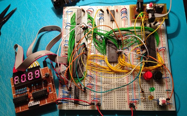
Everyone is having a go at building their own 8-bit 80s-era microcomputer now, and [Petri] thought he would throw his hat into the ring with ERIC-1, a homebrew, 6502-based computer that’s running at about 2MHz.

We’re about 30 or 40 years ahead of the game compared to the old-school 6502 designs, and [Petri] decided to capitalize on that. Instead of a separate ROM, VIA, and other peripherals, [Petri] is connecting a microcontroller directly to the data and address pins. This is a technique we’ve seen before, and [Petri] is doing it right: the micro and 6502 share 64k of RAM, with the ROM stored in the micro’s Flash. Video (PAL in this case) is handled by the ATMega, as is clocking and halting the CPU.

There were a few changes [Petri] made along the way to make this microcomputer a little more useful. One of the biggest changes was switching out the old NMOS Rockwell 6502 with the modern CMOS W65C02 from Western Design Center. The CMOS variant is a fully static design, keeping the registers alive even if the clock is stopped and making single-stepping and halting the CPU easier.

The CMOS variant also has a Bus Enable (BE) pin. Like similar pins on later, more advanced processors, this pin puts the address, data, and R/W pins into a high impedance state, giving other peripherals and microcontrollers the ability to write to RAM, peripherals, or anything else. It’s a handy feature to have if you’re using a microcontroller for everything except the CPU.

It’s already a great build, and since [Petri] has the skills to program this 8-bit ‘duino game, he’s sure to come up with something even better for this computer.

Oh, if you’re looking for something even cooler than a 3-chip 6502, there’s a bunch of stuff over on hackaday.io you should check out. Everything from 4-bit computers built from discrete components to dual AVR board can be found there.

Recovering Colo(u)r From PAL Tele-recordings

You will never see every episode of Doctor Who, and that’s not because viewing every single episode would require a few months of constant binging. Many of the tapes containing early episodes were destroyed, and of the episodes that still exist, many only live on in tele-recordings, black and white films of the original color broadcast.

Because of the high-resolution of these tele-recordings, there are remnants of the PAL color-coding signal hidden away. [W.A. Steer] has worked on PAL decoding for several years, and figured if anyone could recover the color from these tele-recordings, he could.

While the sensors in PAL video cameras are RGB, a PAL television signal is encoded as luminance, Y (R+G+B), U (Y-B), and V (Y-R). The Y is just the black and white picture, and U and V encode the amplitude of two subcarrier signals. These signals are 90 degrees out of phase with each other (thus Phase Alternating Line), and displaying them on a black and white screen reveals a fine pattern of ‘chromadots’ that can be used to extract the color.

Programmable Logic I – PLA/PAL


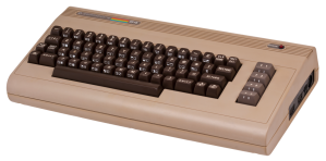
C64-B

Yeah I am still a little pissed that the competition is still around and we aren’t, and by “we” I mean Commodore Business Machines (CBM). It was Commodore that had the most popular home computer ever in the C64 (27 Million) and it was a team of MOS engineers after all, that had the idea to make a “micro” processor out of a 12 square inch PCB.

MOS Technologies logo and address
MOS Technology in King of Prussia/Norristown

Of course they did work at Motorola at the time and “Mot” did not want anything to do with a reduction of the profit margin on the pie-plate size processor. Of course MOS got sued by Motorola but that was an average Tuesday at MOS/CBM. I absolutely credit CBM with buying the MOS Technologies chip foundry, as together we could make our own processors, graphics chips, sound chips, memory controllers, and programmable logic.

With this arsenal at our call we didn’t have to make compromises the way other companies did such as conforming to the bus spec of an industrial standard 6845 or having to add extra logic when a custom extra pin would work. We could also make sprites.

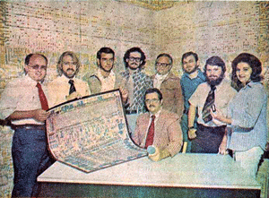
6502 Design Team
6502 Design Team (EE Times 1975, archive.archaeology.org)

The compromise we did have to make when designing was cost, and I mean the kind of cost reduction where finding a way to save a dollar ($1USD) saved millions in the production run. I knocked $.90USD out of a transformer one day and I couldn’t focus the rest of the day due to elation.

Cost reduction is a harsh mistress however as you can’t just do it a little some of the time or only when you want to. The mental exercise of multiplying anything times a million was always there, it made it hard to buy lunch — I’d be blocking the lunch line while figuring the cost of a million tuna sandwiches FOB Tokyo Continue reading “Programmable Logic I – PLA/PAL”

Update From Wayback: AVGA Reborn As RetroWiz

retrowiz-vga-avr-gaming-system

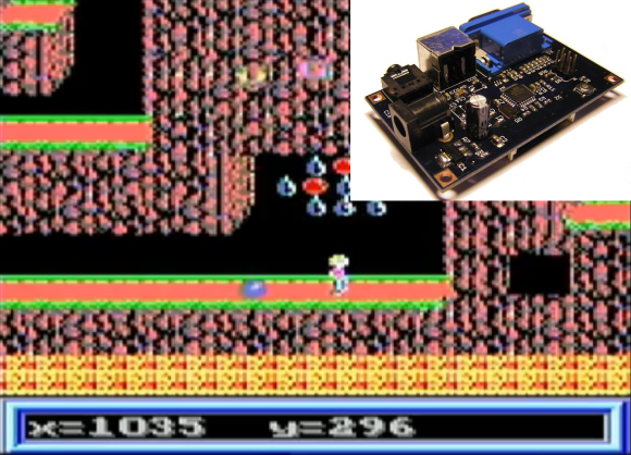
This one has been a long time coming. We’re finally seeing an update to [Jaromir’s] retro gaming platform based around and ATmega chip. The thing that was novel about it back in 2009, and continues to be to this day, is the use of VGA output (PAL) from an AVR chip rather than composite video like most offerings.

Good projects never die and recently he picked the hardware up again, spinning a mostly surface mount board and putting together a new website to feature his work. Above you can see a demo of Commander Keen 4 running on the hardware (video below). He’s also has a rather trippy Super Mario port and adapted [Albert Seward’s] PacMan source for the hardware.

The chip is being clocked at 32MHz with VGA clock running at 19.6608 MHz. This gives him sixteen colors with a resolution of 192×144. He concedes that you get better resolution out of composite video, but who needs resolution for retro gaming?

Continue reading “Update From Wayback: AVGA Reborn As RetroWiz”

Hacking A PAL SNES To Output 50Hz Or 60Hz With A Single Switch

snes-pal-ntsc-mod

[Derecho] grabbed a PAL format Super Nintendo but wanted to make it play nicely with a 60 Hertz NTSC screen. His hack added a single switch to choose between 50 Hz and 60 Hz.

Take a look at the image above to see his alterations to the mainboard. The jumpers soldered to the two chips at the top are by far the trickiest part of the project. Each of the pins he soldered to needed to first be lifted from the PCB pad so that they no longer make contact with the etched traces. The technique he used involves heating the pin with an iron, then gently lifting it with a pin or a razor knife/blade. If you’ve got some experience populating SMD boards with a handheld iron this shouldn’t prove too difficult. The rest of the hack involves adding a 3-position switch (along with a 2k2 resistor) to choose between output modes based on what format game is being played.

Experimenting With 8-bit Graphics

[Vinod] has done a lot of work with microcontrollers, but this is his first try at displaying graphics using composite video. He had a small PAL television on hand, and an ATmega32 which just needs a stable clock source and a few resistors to get things going.

There are a lot of other hacks around that use composite video out with microcontrollers. But this is a ground-up approach which will help you understand the concepts behind these graphics. [Vinod] started by calculating the possible resolution. He needs to hold a frame buffer in memory, and since his chip has just 2 kilobytes of SRAM this will be the limiting factor. He settled on a display area of 128 by 64 pixels. This divides evenly by 8 so he’s not wasting any bits, and it totals 1k, leaving half of the SRAM for use in calculating the shapes which populate the buffer. An interrupt service routine runs ever 64 microseconds to feed data for each line of the display.

With the scanning in place, he moved on to fill the frame buffer. Two functions are used, one which sets a pixel the other clears a pixel. He compares these to using a pencil and an eraser. By calling these functions from his main program he is able to draw lines, boxes, and circles. A bit of creative looping and he’ll have animations as well, but that’s a concept for a different post.

Phasor A/V PAL Demo Uses ATmega88

[youtube=http://www.youtube.com/watch?v=sCN1bqRG-7o]

Above is a new demo video called Phasor developed by [Lft]. It is run from an AVR ATmega88 and a few passive components, and the result is pretty amazing. [Lft] goes into detail about the tricks he used to get this up and running. The chip is clocked at 17.73447 MHz which is exactly four times the frequency of the PAL color carrier wave which allows him to fake a smooth signal. He also uses a timer trick to get the voltages that he needs. The work done here is beyond hardcore and quite frankly we can’t believe he managed to fit all of this into 8.5 KB of program space with just 1 KB or RAM. We wonder if there’s enough room there to add sound and color to the AVR Tetris project.

[Thanks Sprite_tm]