Hard Drive Centrifuge For Sensitizing Copper Clad Boards

hdd-to-apply-light-sensitive-ink

We would wager that most of the home etched PCB projects we see around here use the toner transfer method. But the next most popular technique is to use photosensitive ink which resists the etching acid once it has been exposed to light. Most people buy what are called pre-sensitized boards, but you can also get ink to make your own. [Jardirx] does this, and uses an old hard drive to apply an even layer of the light-sensitive ink.

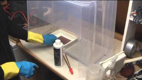
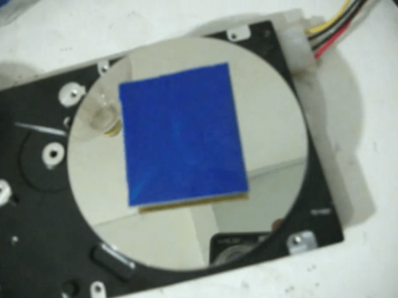
The narration and subtitles of the video found after the break are both in Portuguese, but it’s not hard to figure out what’s going on here. He begins by using double-sided foam tape to secure the piece of copper clad board to the hard drive platters. You’ll want to center it as best as you can to keep the vibrations to a minimum. From there [Jardirx] applies a coating of the ink using a brush. The image above is what results. So as not to get ink everywhere, he then lowers a soda bottle with the bottom cut off to catch the excess. Power up the drive for a few seconds and the board will have a nice even layer ready for a trip through a UV exposure box.

Continue reading “Hard Drive Centrifuge For Sensitizing Copper Clad Boards”

[Fran’s] PCB Etching Techniques

frantronics-pcb-tutorials

We think that anyone who’s done at-home PCB fabrication will appreciate the tidiness that [Fran] maintains throughout her etching process. She recently posted a three-part video tutorial which showcases her techniques. As you can see in the screenshot above, her habits reek of top-notch laboratory skills.

Regular readers can probably guess what circuit she’s etching. It’s the test boards for her LVDC reverse engineering. She is using the toner transfer method, but in a bit different way than most home-etchers do. She uses the blue transfer paper made for the job, but before transferring it to the copper clad she uses a light box (kind of like the X-ray film viewer at the doctor’s office) to inspect for any gaps where toner did not adhere. From there she uses a heat press to apply the resist. This is a heck of a lot easier than using a clothes iron, but of course you’ve got to have one of these things on hand to do it this way.

The second part of the tutorial is embedded after the break. We chose this segment because it shows off how [Fran] built her own chemical hood. It’s a clear plastic storage container lying upside down. A work window has been cut out of the front side, and a 4-inch exhaust hose added to the top. [Fran’s] lab has a high volume low velocity fan to which it connects to whisk the fumes outside.

Continue reading “[Fran’s] PCB Etching Techniques”

Modifying A Printer For PCB Fabbing

ohgodmyeyes

The migraine-inducing image above is the product of [Rupert Hirst]’s attempts at home PCB fabrication. He’s using the toner transfer method – printing a circuit on a piece of transparency sheet with a laser printer, setting it on a piece of copper clad board, and sending the whole assembly through a laminator. It’s a fairly straightforward process, but if you can’t run a transparency sheet through a printer multiple times your etch resist won’t hold up too well. Of course the transparency sheet must be aligned each time it goes through the printer, so [Rupert] came up with a modification that ensures laser toner goes only where it’s supposed to.

[Rupert] picked up a Samsung ML-2165W laser printer for his PCB fab shop, but printing the same image multiple times on the same transparency sheet would result in unusable masks. This problem was fixed with a few plastic shims used to hang door frames and a card stock tray that ensures the transparency sheet goes through the printer the same way every time.

We saw [Rupert]’s homebrew PCB fabrication process a few weeks ago when he sent in his six channel floppy drive MIDI synth. In his build video, [Rupert] demonstrated what is possibly the cleanest toner transfer PCB we’ve seen to date. You can check out his etching process in the video after the break.

Continue reading “Modifying A Printer For PCB Fabbing”

Panelizing PCBs In Eagle

final_panel

A lot of the board houses out there including Seeed and ITead studios have a fixed size for circuit boards before the price goes up. A one-inch square board costs the same as a much larger 5cm x 5cm board, making panelized PCBs a great way to get more boards for the same amount of money. Trying to panelize a board in Eagle with copy and paste is a chore without the right tools, though, so we’re happy to see a great panelization tutorial from [Victor].

To panelize one of his boards for a PCB order, [Victor] used one of Eagle’s User Language Programs to duplicate the part names on the additional boards. After that, it was a simple matter of running a CAM job to generate the necessary Gerber files.

Of course once the boards arrive, you’ll have to cut them apart from each other. This can be done with everything from a Dremel to a hack saw to a metal shear, but we’re wondering what other Hackaday readers are using to cut up PCBs. Leave a note in the comments with your preferred method of depanelization.

Making Eagle Work With Circuits.io

IO

Ever so slowly, we’re inching towards a world of Internet-based electronic design tools. The state of these tools, including Upverter and other cloud-based solutions, hasn’t been all that great until now; with any new piece of schematic capture and PCB layout software, the libraries will be woefully inadequate in the beginning. This is about to change, because circuits.io is now allowing Eagle libraries to be imported.

As you may well be aware, Eagle is the de facto standard for homebrew and hobbyist schematic capture and board layout software. Even though Eagle isn’t open source and is limited to rather small PCBs with the free version, somehow Eagle has retained its popularity, most likely due to the huge number of component libraries available.

By allowing users and designers to import Eagle libraries, the folks at circuits.io are capitalizing on a huge amount of work done by designers and engineers over the years in creating custom Eagle parts for just about every component imaginable. It’s a great accomplishment for the circuits.io team and a boon for anyone wanting to move their PCB design tools over to the cloud.

Via Press Crushes Copper To Make A Mechanical Connection

via-press-in-action

[Jay] was looking for a way to make his own vias on homemade double-sided PCBs when he stumbled across this post from about five years ago. The technique shown here makes mechanical vias and was developed by [Retromaster]. There’s no soldering involved, instead he uses some solid core copper wire and a press to crush it tightly against the board.

The press is made from aluminum stock, with a couple of plates of stainless steel which come in contact with the board. The aluminum stock is easy to work with, but it’s relatively soft which is the reason for the addition of steel. He uses copper wire which already fits tightly in the hole through the substrate. After clipping off the excess as near to the board as possible a trip through the press leaves each side flat as shown in the inset image.

We looked through some of the other projects we’ve seen from [Retromaster] like the Atari 2600 in an FPGA and this emulated Amiga floppy drive. But we didn’t see any diy boards where he used this crushing technique.

Building A Six-channel Floppy Drive Synth From Start To Finish

floppy

We’ve seen scores of floppy drives play music, but never before have we seen a project as clean as [Rupert]’s Moppyduino. It’s an Arduino-based board that controls the stepper motors in six separate floppy drives, coaxing them in to playing music from a MIDI file.

The Moppyduino is more than just a convenient way to control the stepper motors in six floppy drives. It’s also a great example of what can be done with home PCB fabrication; the entire project was designed and constructed in [Rupert]’s workshop.

After designing the circuit, [Rupert] printed it out on a laser printer onto a plastic transparency sheet. This was transferred over to a copper clad board, etched, and drilled. After assembly, [Rupert] attached a USB FTDI controller to receive data converted from MIDI data with a Java app.

The end result – housed in a custom Corian enclosure – is one of the best looking floppy drive synths we’ve ever seen. You can check out the process of building this awesome instrument after the break.

Continue reading “Building A Six-channel Floppy Drive Synth From Start To Finish”