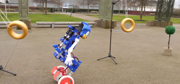
Flying With Proportional – Integral – Derivative Control

Your quad-copter is hovering nicely 100 feet north of you, its camera pointed exactly on target. The hover is doing so well all the RC transmitter controls are in the neutral position. The wind picks up a bit and now the ‘copter is 110 feet north. You adjust its position with your control stick but as you do the wind dies and you overshoot the correction. Another gust pushed it away from target in more than one direction as frustration passes your lips: ARGGGHH!! You promise yourself to get a new flight computer with position hold capability.

How do multicopters with smart controllers hold their position? They use a technique called Proportional – Integral – Derivative (PID) control. It’s a concept found in control systems of just about everything imaginable. To use PID your copter needs sensors that measure the current position and movement.

The typical sensors used for position control are a GPS receiver and an Inertial Management  Measurement Unit (IMU) made up of an accelerometer, a gyroscope, and possibly a magnetometer (compass). Altitude control would require a barometer or some other means of measuring height above ground. Using sensor fusion techniques to combine the raw data, a computer can determine the position, movement, and altitude of the multicopter. But calculating corrections that will be just right, without over or undershooting the goal, is where PID comes into play. Continue reading “Flying With Proportional – Integral – Derivative Control”

PID balancing a ball on a plate

Stewart Platform Ball Bearing Balancer

For their Mechanical Engineering senior design project at San Jose State University, [Tyler Kroymann] and [Robert Dee] designed and built a racing motion simulator. Which is slightly out of the budget of most hackers, so before they went full-scale, a more affordable Arduino powered Stewart platform proof of concept was built. Stewart platforms typically use six electric or hydraulic linear actuators to provide motion in six degrees of freedom (6 DOF), surge (X), sway (Y), heave (Z), pitch, roll, and yaw. With a simple software translation matrix, to account for the angular displacement of the servo arm, you can transform the needed linear motions into PWM signals for standard hobby servos.

The 6 DOF platform, with the addition of a resistive touch screen, also doubled as a side project for their mechatronic control systems class. However, in this configuration the platform was constrained to just pitch and roll. The Arduino reads the resistive touch screen and registers the ball bearing’s location. Then a PID compares this to the target location generating an error vector. The error vector is used to find an inverse kinematic solution which causes the actuators to move the ball towards the target location. This whole process is repeated 50 times a second. The target location can be a pre-programmed or controlled using the analog stick on a Wii nunchuck.

Watch the ball bearing seek the target location after the break.

Thanks to [Toby] for sending in this tip.

Continue reading “Stewart Platform Ball Bearing Balancer”

Replicator 1 Receives A PID Controlled Heated Chamber

Replicator 1 PID Heated Enclosure

Improving 3D print quality is a bit of a black magic — there are tons of little tweaks you can do to your printer to help it, but in the end you’re just going to have to try everything. Adding a heated build enclosure however is one of those things almost guaranteed to improve the print quality of ABS parts!

And for good reason too — heated build enclosures are one of the outstanding “patented 3D printing technologies” — It’s why you don’t see any consumer printers with that feature. Anyway, [Bryan] just sent us his upgrade to his Makerbot Replicator 1, and it’s a pretty slick system. His goal was to add the heated enclosure to the printer as unobtrusively as possible — no need for people to think his printer is an even bigger fire hazard!

Continue reading “Replicator 1 Receives A PID Controlled Heated Chamber”

PIDDYBOT – A Self Balancing Teaching Tool

We’re sure that most Hackaday readers are already familiar with the inverted pendulum system, which basically consists of a pendulum having its center of mass above its pivot point. Most applications (like the one we are going to describe) limit the pendulum to 1 degree of freedom by affixing the pole (or circuit board here) to an axis of rotation. The overall system is therefore inherently unstable and must be actively balanced in order to remain upright.

[Sean] created the piddybot, a tiny balancing robot aimed to teach the basics of PID control by trying to get the robot to stand still. More interestingly, the Proportional / Integral / Derivative values can directly be adjusted using the three on-board potentiometers. This will allow users to get the feel of each parameter’s impact on the robot behavior. The piddybot is based around the Arduino nano, a custom PCB, 2x 26:1 geared motors, one 1A dual motor driver board, a six degrees of freedom Inertial Measurement Unit, 2 batteries and finally a 3D printed body. You can check out a video of the robot in action after the break.

This project stems from a non-PID self balancer which [Sean] hacked together in September.

Continue reading “PIDDYBOT – A Self Balancing Teaching Tool”

Kitchen Hacks: Improving An Espresso Machine

The heat sensor in [Cameron]’s espresso machine doesn’t work very well. He sees some pretty crazy variations in temperature when pulling an espresso shot, and when the boiler is just sitting there the heater element will heat the water full-bore then shut off for a while. Since this is a pretty low bar from a control theory standpoint, [Cameron] decided on a PID makeover on his espresso machine.

Instead of going with a commercial PID controller like we’ve seen on a few kitchen hacks, [Cameron] decided to roll his own Arduino derivative based on an ATMega328 microcontroller. The newly designed board reads the state of the ‘Steam’ button, a few relays for controlling the heater and the pump, and of course an LCD display.

[Cameron] still has to do a little tweaking to get his PID algorithm down, but already the new control board keeps a much more stable temperature than the old thermostat. The fancy new bezel and LCD display adds a lot of techy class to his espresso machine, to boot.

Silvia PIC Controlled PID Looped Espresso Machine


Last night I rebuilt my ECM Giotto with a new boiler. I’ve seen PID controlled machines before, but today I stumbled across this modded Rancillo Silvia. [Tim] replaced the internal brain with a PIC controller, added a NES control pad for input, a VFD display and a custom laser cut acrylic top. He used the PIC to provide PID control and PWM heater control with the usual solid state relays. I was leaning towards using a PIC for PID control myself, but then I scored my Giotto. (The heat exchanger and larger boiler makes it a bit of a moot point, but I’m still tempted to add PID boiler controls.)