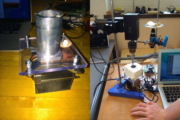
A while ago, [Kyle] built an automated mushroom cultivator. This build featured a sealed room to keep contaminants out and enough air filtering and environmental controls to produce a larger yield of legal, edible mushrooms than would otherwise normally be possible.
Now, he’s at it again. He’s expanded the hardware of his build with a proper, grounded electrical box for his rig, added more relays, implemented PID for his temperature and humidity controller, and greatly expanded the web interface for his fungiculture setup.
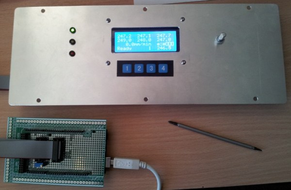
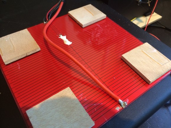
Like the previous versions of his setup, this grow chamber is controlled by a Raspberry Pi with a camera and WiFi module. Instead of the old plastic enclosure, [Kyle] is stepping things up with a proper electrical enclosure, more relays, more humidity and temperature sensors, and a vastly improved software stack. Inside the enclosure are eight relays for heaters and humidifiers. The DHT22 sensors around the enclosure are read by the Pi, and with a proper PID control scheme, controlling both the temperature and humidity is simply a matter of setting a number and letting the machine do all the work.
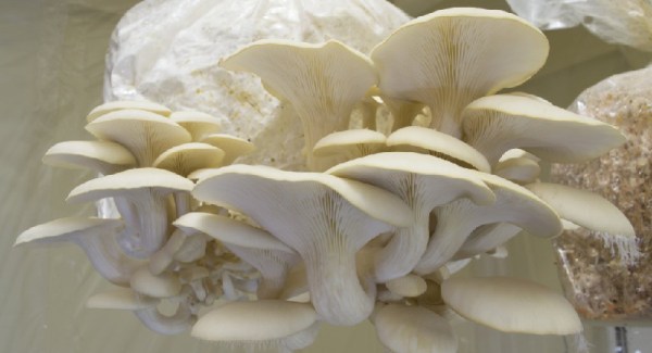
The fungi of [Kyle]’s labor include some beautiful pink and white oyster mushrooms, although with a setup like this there’s not much fungiculture he can’t do.