Starlink: A Review And Some Hacks

I could probably be described as a SpaceX enthusiast. I catch their launches when I can, and I’ve watched the development of Starship with great interest. But the side-effect of SpaceX’s reusable launch system is that getting to space has become a lot cheaper. Having excess launch capacity means that space projects that were previously infeasible become suddenly at least plausible. One of those is Starlink.

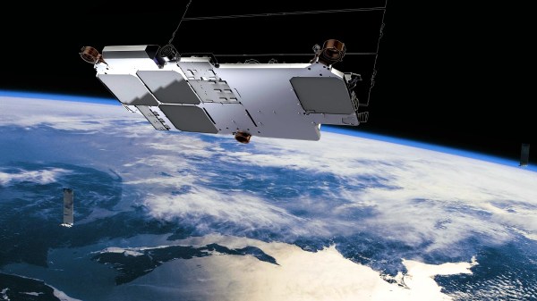
Starlink is SpaceX’s satellite Internet service. Wireless and cellular internet have helped in some places, but if you really live out in the sticks, satellite internet is your only option. And while satellite Internet isn’t exactly new, Starlink is a bit different. Hughesnet, another provider, has a handful of satellites in geostationary orbit, which is about 22,000 miles above the earth. To quote Grace Hopper, holding a nearly foot-long length of wire representing a nanosecond, “Between here and the satellite, there are a very large number nanoseconds.”

SpaceX opted to do something a bit different. In what seemed like an insane pipe dream at the time, they planned to launch a satellite constellation of 12,000 birds, some of them flying as low as 214 mile altitude. The downside of flying so low is that they won’t stay in orbit as long, but SpaceX is launching them significantly faster than they’re coming down. So far, nearly 1,600 Starlink satellites are in orbit, in a criss-crossing pattern at 342 miles (550 km) up.

This hundred-fold difference in altitude matters. A Hughesnet connection has a minimum theoretical latency of 480 ms, and in reality runs closer to 600 ms. Starlink predicts a theoretical minimum of under 10 ms, though real-world performance isn’t quite that low yet. In the few weeks I’ve had the service, ping times have fallen from mid-60s down to 20s and 30s. The way Starlink works right now, data goes up to the closest satellite and directly back to the connected ground station. The long-term plan is to allow the satellites to talk directly to each other over laser links, skipping over the ground stations. Since the speed of light is higher in a vacuum than in a fiber-optic cable, the fully deployed system could potentially have lower latency than even fiber Internet, depending on the location of the endpoint and how many hops need to be made.

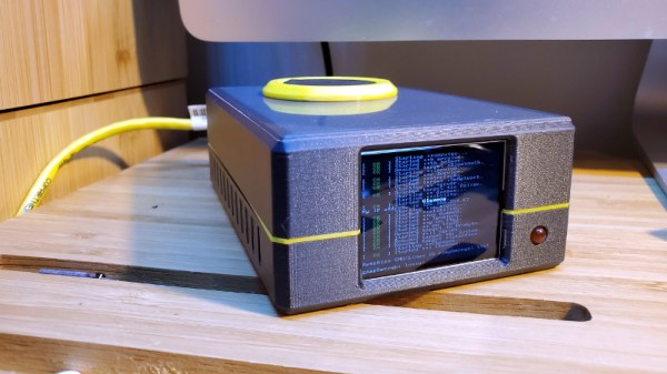
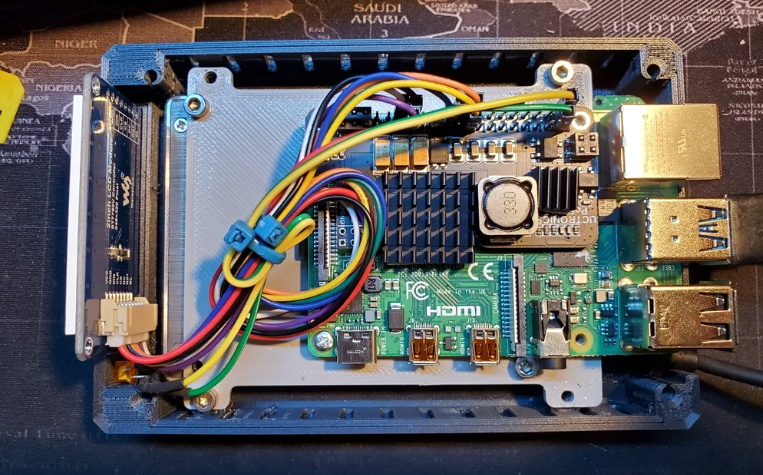
I got a Starlink setup, and have been trying out the beta service. Here’s my experience, and a bonus hack to boot.

Continue reading “Starlink: A Review And Some Hacks”

A Cyclopic LCD Case For Your Raspberry Pi Server

If you’ve got a personal website that needs hosting or a few hundred gigabytes of files that could use a centralized storage location, the Raspberry Pi’s small size and extreme energy efficiency make it a compelling server choice compared to that curbside Pentium 4 box you’ve been trying to find a home for. All you need is something to put in.

Of course there’s no shortage of Pi case designs ready to be extruded from your 3D printer, but we recently found ourselves particularly taken with this unique one designed by [Ken Segler]. It’s not only small and sleek with a dash of futuristic flair, but it includes a front-mounted two inch 240 x 320 IPS display that connects to the Pi over SPI. At the minimum that gives you a way to see all those beautiful boot messages on startup, but with a little code, it could provide you with various system statics and status messages at a glance.

While the LCD is clearly the star of the show here, the case also has a few other nice features that make it worthy of your consideration. The magnetically attached fan filter on the the top, for one. The stacked layout that puts the Pi directly above the SSD also makes for a relatively compact final product.

One thing to note though is that [Ken] is using Power-over-Ethernet, meaning there’s no spot for a dedicated power jack on the case. It’s an easy enough feature to add into your own build, but naturally not everyone’s network is suitably equipped. In that case, beyond the normal annoyances of editing STL files, it shouldn’t be too much trouble to add one in without having to literally hack your way through the printed plastic.

A Network Attached VFD Tube Clock

The elegance of Power over Ethernet (PoE) is that you can provide network connectivity and power over a single cable. Unfortunately not nearly enough hardware seems to support this capability, forcing intrepid hackers to take matters into their own hands. The latest in this line of single-cable creations is this beautiful Vacuum Fluorescent Display (VFD) clock from [Glen Akins].

Testing the VFD tube socket

One of the key advantages VFDs have over their Nixie predecessors is greatly reduced energy consumption, and after [Glen] ran the numbers, he saw that a display using six VFD tubes could easily be powered with standard PoE hardware. With this information, he started designing the PCB around the early 1990s era IV-12 tube, which has the advantage of being socketed so he could easily remove them later if necessary.

[Glen] first had to create a schematic and PCB footprint for the IV-12 tube that he could import into Eagle, which he was kind enough to share should anyone else be working with these particular tubes down the line. After a test of the newly designed socket was successful, he moved onto the rest of the electronics.

The clock is powered by a Microchip PIC18F67J60, which connects to the Ethernet network and pulls the current time down from NTP. After seeing so many clocks use an ESP to connect to the Internet over WiFi, there’s something refreshing about seeing a wired version. The tube segments are driven by a HV5812, also Microchip branded. Lastly, [Glen] used a number of DC/DC converters to generate the 1.5 V, 3.3 V, 5 V, and 25 V necessary to drive all the electronics and VFDs.

We absolutely love the simplicity of this clock, from its sleek aluminum enclosure to that single RJ45 jack on the back. But if you’re looking for something with a bit more flash, [Glen] also put together some PoE Christmas lights over the holidays which share a number of design elements with this project.

Continue reading “A Network Attached VFD Tube Clock”

PoE Powers Christmas Lights, But Opens Up So Much More

Addressable LEDs are a staple of homemade Christmas decorations in our community, as is microprocessor control of those LEDs. So at first sight [Glen Akins]’ LED decorated Christmas tree looks pretty enough, but isn’t particularly unusual. But after reading his write-up you’ll discover there’s far more to the project than meets the eye, and learn a lot about the technologies behind it that has relevance far beyond a festive light show.

The decoration is powered exclusively from power-over-Ethernet, with a PIC microcontroller translating Art-Net DMX-over-Ethernet packets into commands for the LED string. The control board is designed from the ground up and includes all the PoE circuitry, and the write-up  gives a very thorough introduction to this power source that takes the reader way beyond regarding PoE as simply another off-the-shelf black box. Along the way we see all his code, as well as learn a few interesting tidbits such as the use of a pre-programmed EEPROM containing a unique MAC address.

So if your house has CAT5 wiring and you want an extra dimension to your festive splendour, you’ve officially got a whole year to build your own version. He’s featured here before, with his buzzer to break the Caps Lock habit.

Continue reading “PoE Powers Christmas Lights, But Opens Up So Much More”

Using PoE With A Raspberry Pi 3 For About Two Bucks

When the Raspberry Pi 3 Model B+ was announced in March of 2018, one of its new features was the ability to be (more easily) powered via Power-over-Ethernet (PoE), with an official PoE HAT for the low price of just twenty-one USA bucks. The thing also almost worked as intended the first time around. But to some people this just isn’t good enough, resulting in [Albert David] putting out a solution he calls “poor man’s PoE” together for about two bucks.

His solution makes it extra cheap by using so-called passive PoE, which injects a voltage onto the conductors of the network cable being used for PoE, without bothering with any kind of handshake. In general this is considered to be a very reliable (albeit non-standard) form of PoE that works great until something goes up in smoke. It’s also ridiculously cheap, with a PoE injector adapter (RJ-45 plug & 2.1×5.5 mm power jack to RJ-45 jack) going for about 80 cents, and a DC-DC buck converter that can handle the input of 12V for about 50 cents.

The rest of the $2 budget is mostly spent on wiring and heatshrink, resulting in a very compact PoE solution that plugs straight into the PoE header on the Raspberry Pi 3 board, with the buck converter outputs going into the ground and +5V pins on the Raspberry Pi’s GPIO header.

A fancier solution would implement any of the standard PoE protocols to do the work of negotiating a suitable voltage. Maybe this could be the high-tech, $5 solution featuring an MCU and a small PCB?

Cheap Power Over Ethernet For The ESP32

While most projects we see with the ESP32 make use of its considerable wireless capabilities, the chip can be connected to the wired network easily enough should you have the desire to do so. [Steve] liked the idea of putting his ESP32s on the wired network, but found the need for a secondary power connection burdensome. So he took it upon himself to modify some cheap Power Over Ethernet (PoE) hardware and create a single-cable solution (Google Translate).

[Steve] bought a PoE module intended for security cameras and ran a close eye over the board to figure out what kind of hardware it was using to generate the nominal 12 V output. He identified an MP2494 step-down converter, and with the datasheet in hand found how the output voltage is configured by changing the values of resistors in the circuit. Swapping out the stock 21.5 kΩ resistor for a 57.1 kΩ one changed the output of the converter to the 5 V necessary for his electronics.

But of course that was only half of the problem solved; he still had to connect the Ethernet side of the PoE device to the Waveshare LAN8720 board that’s providing Ethernet for the ESP32. So he removed the RJ45 jack from the LAN8720 completely, and wired that directly to the connector on the PoE board. Helpfully, the PoE board had all the pins labeled on the bottom side so this wasn’t nearly as tricky to figure out as you might expect (if only it was always that easy).

We’ve previously covered the Waveshare LAN8720 board for anyone who’s interested in the ins and outs of getting their ESP32 talking Ethernet. If you’re wondering how you can put PoE to work for you, our very own [Jonathan Bennett] has been showing off his home Raspberry Pi infrastructure which makes extensive use of the new PoE hat.

Raspberry Pi PoE Redux

[Martin Rowan] was lucky enough to get his hands on the revised Power Over Ethernet (PoE) hat for the Raspberry Pi. Lucky for us, he wrote it up for our benefit, including inspection of the new hat, it’s circuit, and electrical testing to compare to the original hardware.

You may remember the original release of the PoE hat for the Raspberry Pi, as well as the subsequent recall due to over-current issues. In testing the revised board, [Martin] powered a test load off the USB ports, and pulled over an amp — The first iteration of the PoE hat would often trip the over-current protection at 300 milliamps.

This afternoon, the redesigned PoE board was officially released, and the post mortem of the problem documented in a blog post. It’s a lesson in the hidden complexity of hardware design, as well as a cautionary tale about the importance of thorough testing, even when the product is late and the pressure is on.

The PoE hat converts 48 volt power down to a 5 volt supply for the Pi using a flyback transformer. The problem was that this transformer setup doesn’t deliver clean steady 5 volt power, but instead provides power as a series of spikes. While these spikes were theoretically in spec for powering the Pi and usb devices, some Raspberry Pis were detecting those spikes as too much current pushed through the USB ports. The official solution essentially consists of better power filtering between the hat and the Pi, flattening that power draw.

We’re looking forward to getting our hands on this new and improved PoE Hat, and using it in many project to come.