The Force Is Strong With This Christmas Tree Light Show

star-wars-christmas-tree

[Zach] is a huge Star Wars fan, and in addition to the array holiday decorations that adorn his house, he says that his wife is nice enough to let him put up a Christmas tree full of Star Wars ornaments. For the past few years, the tree sat in the corner of the room unlit, but his wife thought that it should have some lights this year.

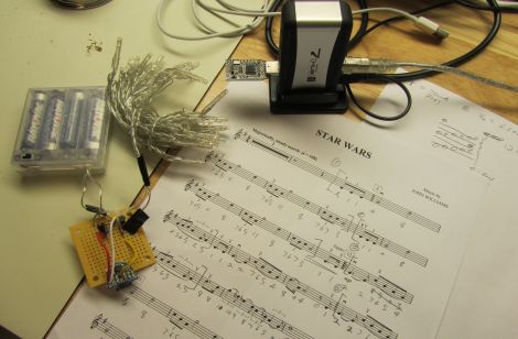
His wife came home with a small string of battery-operated lights, but [Zach] wanted something with a bit more geek cred. He decided to program the lights to play the Star Wars theme song, translating the tune’s pitch to light intensity.

He dug through his bin of electronics and found an MSP430 along with a small target board that would do the job nicely. He sat down with some sheet music, translating the notes to PWM values, resulting in the light show you see below.

While his wife provided a lovely violin accompaniment to the tree, we think that a small audio module would make a great addition to the tree next year.

Continue reading “The Force Is Strong With This Christmas Tree Light Show”
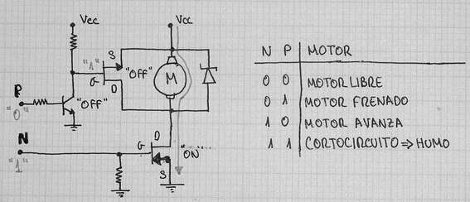
Motor Drivers: Half H-bridge With Brake And More

Here’s a nice little circuit that will drive a motor and allow you to stop its rotation, giving your robot a set of brakes. It’s part of [JM’s] post about the in’s and out’s of building microcontroller friendly motor controllers (translated).

This particular setup is a half H-bridge. It allows you to drive the motor in one direction only. The MOSFET used on the ground-side of the motor doesn’t actually need to be there. This is the brake which let you electronically stop the motor from spinning. Without it, the motor will keep turning under its own momentum when the half-bridge is shut off. Depending on the application this can be a big problem. There’s a great demonstration of the circuit braking a fast spinning motor in the video clip below the fold.

It is possible to use this driver with PWM, but [JM] has some warnings about inbuilt functions like FastPWM. Make sure you read his admonition, and if you need a refresher don’t miss this Hackaday video segment.

Continue reading “Motor Drivers: Half H-bridge With Brake And More”

Detailed Tutorial Shows How To Unleash Your Inner [Michael Knight]

developing_a_larson_scanner

Our own [Mike Szczys] recently sat down and put together a great tutorial on building a Larson Scanner. The ubiquitous circuit is usually one of the first few projects on a budding hackers list of things to build, since they are just so darn fun.

Simple versions of the scanner sweep back and forth lighting the LEDs without any sort of transition between them. The configuration most familiar to us all as featured in Knight Rider and Battlestar Galactica are a bit more complex, and have a fading trail of light that follows behind the leading edge of the sweep. [Mike] notes that this fading is traditionally accomplished through the use of capacitors, which cause the light to gradually fade as the animation sweeps across the LED array. He decided to take a different route with his circuit, relying on PWM control of the LEDs instead.

Mike put together a simple circuit using an ATmega168, a handful of resistors, and of course, an array of LEDs. Utilizing interrupts and PWM, he was able to accurately recreate the iconic light sweep without the use of any capacitors. One big benefit to his design aside from the lower component count is the fact that he can easily adjust the speed of the sweep as well as the fading properties with a few small code tweaks.

Be sure to check out his blog at some point, where he shares his code, some circuit diagrams, and plenty more details on how his scanner was built. In the meantime, take a look at the video below to see the result of [Mike’s] work.

Continue reading “Detailed Tutorial Shows How To Unleash Your Inner [Michael Knight]”

Converting PWM To DC Signaling For More Precise Fan Control

pwm_to_dc_fan_control

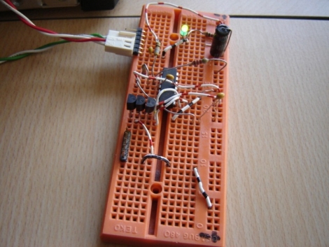
[hedgehoginventions] wrote in to share a little modification he made to his video card in order to keep it from overheating during strenuous 3D tasks. Having swapped out the stock cooler on his Nvidia 9600GT graphics card, he found that it did not need to utilize the fan while doing mundane things like checking email, but that it still required extra air flow while playing games.

He figured he get the fan to shut off by tweaking the PWM signal, but he found that he could not get the duty cycle under 20% using software, which still caused the fan to run at all times. The circuit he built takes the PWM signal output by the card, cleaning it up before converting it to a corresponding DC voltage. The fan then runs at the same speed it would if driven directly by the PWM signal, though it can now turn off completely when not required.

It’s a nice way to do automatic fan control when you can’t otherwise get your GPU fan to shut off. Nice work!

An Introduction To DC Boost Converters

simple_boost_converter

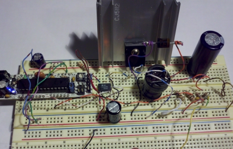
If you are planning on creating some sort of Nixie tube display, you will undoubtedly need to find yourself a high voltage DC power supply. If you don’t want to add a transformer to your project, you can always opt to build a boost converter instead. [Andrew Moser] shows us just how easy it is to build one, discussing the theory behind simple boost converters along the way.

Boost converters are often driven by dedicated ICs, but in this case the PWM signal from an Arduino does the job just fine. [Andrew] covers the process of choosing the proper components for the circuit, discussing duty cycles and components to avoid lest your boost converter die an untimely death.

He shows us how to implement a feedback system to get a more precise output voltage, but as Lady Ada has shown us, an open loop works pretty well too.

For the beginners that want to just get things up and running, his instructions and code should be sufficient, but [Andrew] provides plenty of reference links for those looking to delve deeper into the subject.

Update: Arduino Shift Register PWM Gets Speed Boost

Community collaboration is a great thing. Take the Arduino PWM library for shift registers. Some folks at the Arduino forum pitched in and helped [Elco] trim off a bunch of clock cycles by using the Rotate Over Carry instruction. Now he’s reduced the overhead per shift-register from 108 down to just 43. So far this doesn’t mean more possible outputs – 768 is still quite a lot – but does it means better precision when max outputs are used. This effectively doubles the brightness levels for 768 LEDs from 16 up to 32.

We’re at a loss for what to link to here. [Elco] has a new page for the library. There’s the original forums thread but we didn’t see much of interest there. We found some stuff in the comments of this Reddit post. And of course, if you have no idea what we’re talking about go back and read the original feature.

Using Binary Code Modulation To Control LED Brightness

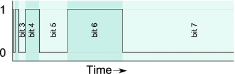
Pulse Width Modulation is definitely the preferred method of dimming an LED with a microcontroller, but we were interested in hearing about a different method called Binary Code Modulation. BCM does the same thing as PWM, it turns the LED on and off very rapidly so that your eye cannot detect a flicker. The brightness level is a result of the average amount of time the LED is on versus when it is off. This is called duty cycle and although it can be the same percentage for both PWM and BCD, there is a fundamental difference.

While PWM usually uses a cyclical on/off cycle (30% on, 70% off, repeat) BCD uses a cumulative cycle. As you can see above, each successive bit of binary code carries double significance compared to the previous bit. Now just assign a duty cycle based on your precision, and have an interrupt fire for each bit of the counter. The graph above shows some highs and some lows combining to reach the target duty cycle. An interrupt is used for each bit, and pin changes are made in the service routine.

The benefit of this system is that it is scaleable without adding overhead. You’re already running the interrupts so servicing 8 or 128 LEDs doesn’t have vastly different needs as it would with PWM. The big downside is that the more bits of precision you use, the faster your processor must run so that the eye doesn’t detect the lengthy on or off cycles of the higher bits as visible flickering.

Thank you [Yetihehe] for tipping us off about a link that [Tomas Martinsen] left when commenting about an Arduino library for up to 768 PWM outputs.