Cyber Monday may be behind us, but there are always some hackable, inexpensive electronics to be had. [Stephen’s] wireless Android/Arduino outlet hack may be the perfect holiday project on the cheap, especially considering you can once again snag the right remote controlled outlets from Home Depot. This project is similar to other remote control outlet builds we’ve seen here, but for around $6 per outlet: a tough price to beat.
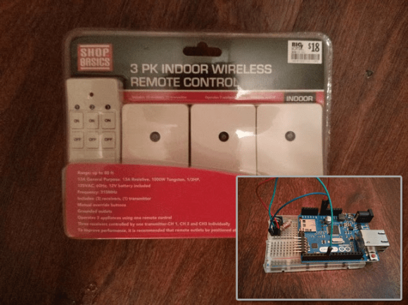
[Stephen] Frankenstein’d an inexpensive RF device from Amazon into his build, hooking the Arduino up to the 4 pins on the transmitter. The first step was to reverse engineer the communication for the outlet, which was accomplished through some down and dirty Arduino logic analyzing. The final circuit included a standard Arduino Ethernet shield, which [Stephen] hooked up to his router and configured to run as a web server. Most of the code was borrowed from the RC-Switch outlet project, but the protocols from that build are based on US standards and did not quite fit [Stephen’s] needs, so he turned to a similar Instructables project to work out the finer details.
Stick around after the break for a quick video demonstration, then check out another wireless outlet hack for inspiration.