How To Reverse Engineer A PCB

For [Peter]’s entry for the 2015 Hackaday Prize, he’s attempting to improve the standard industrial process to fix atmospheric nitrogen. Why? Fertilizers. He’s come up with an interesting technique that uses acoustic transducers in a pressure vessel, and to power that transducer, he’s turned to the greatest scrap heap in the world: eBay. He found a cheap ultrasonic power supply, but didn’t know offhand if it would work with his experiments. That’s alright; it’s a great opportunity to demo some basic reverse engineering skills.

A few months ago, [Dave Jones] posted a great video where he reverse engineers the front end of the new Rigol Zed. The basic technique is to make a photocopy, get some transparency sheets, grab a meter, and go to town. [Peter]’s technique is similar, only he’s using digital image manipulation, Photoshop, and a meter.

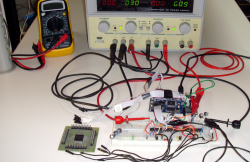
The process begins by taking pictures of both sides of the board, resizing them, flipping one side, and making an image with several layers. The traces on the bottom of the board were flooded and filled with the paint bucket tool, and components and traces carefully annotated.

With some effort, [Peter] was able to create a schematic of his board. He doesn’t know if this power supply will work with his experiments; there’s still some question of what some components actually do. Still, it’s a good effort, a great learning opportunity, and another log in [Peter]’s entry to The Hackaday Prize

Reverse Engineering Galaga To Fix The No-Fire Cheat

We didn’t know there was a cheat to Galaga, but [Chris Cantrell] did. And so he did what any curious hacker would do — reverse-engineer the game to diagnose and eventually fix the bug.

Spoilers ahoy! Go read the website first if you’d like to follow [Chris]’s reversing efforts in the order that they actually happened.

The glitch is triggered by first killing most of the bees. When only six are left, they go into a second pattern where they swoop across the screen and wrap around the edges. While swooping, sometimes the bees will fire a shot when they’re at coordinates with X=0. Now two facts: there’s a maximum of eight missiles on the screen at any given time, and the position X=0 was reserved by the software to hide sprites that don’t need updating.

The end result is that eight missiles get stuck in a place where they never drop and don’t get drawn. No further shots are fired in the entire game. You win.

So that’s the punchline, but everyone knows that a good joke is in the telling. If you’re at all interested in learning reverse engineering, go read [Chris]’s explanations and work through them on your own.

And here’s our generic plug for Computer Archaeology:

Ancient video games run on MAME or similar emulators are the perfect playground for learning to reverse engineer; you can pause the machine, flip a bit in memory, and watch what happens next. Memory was expensive back then too, so the games themselves are small. (It’s not like trying to reverse engineer all however many jiggabytes of Microsoft Office.) The assembly languages for the old chips are small and well-documented, and most of the time you’ve also got a good dissasembler. What more could you ask for?

A walkthrough tutorial?  We’ve just given you one.

Oh and PS: If you get past level 255, the game freaks out.

Continue reading “Reverse Engineering Galaga To Fix The No-Fire Cheat”

Reverse-Engineering A Wireless BBQ Thermometer

[Bob] has his own smoker and loves to barbecue, but doesn’t like spending all day checking on his smoker’s temperature. He thought about building his own wireless thermometer setup, which would have been pretty awesome, but then he had a better idea: why not hack an existing wireless barbecue thermometer? [Bob] purchased an off-the-shelf wireless BBQ thermometer and reverse-engineered its wireless protocol to make his own wireless thermometer setup.

The first problem [Bob] encountered was figuring out the frequency of the transmitter. Thankfully [Bob] had access to a spectrum analyzer, where he discovered the transmitter was running at 433.92MHz (a cheap RTL-SDR dongle would also get the job done). Next, [Bob] started digging into the manufacturer’s FCC filings and found that it actually called out the transmit frequency, which matched the transmit frequency he measured. He also found a ton of other helpful information in the filing, like a block diagram and full transmitter schematic.

[Bob] used a Radiometrix RF module to receive the thermometer’s signal. He hooked up the output to his logic analyzer to start decoding the protocol. After a quick visual analysis, [Bob] found that the signal was a preamble followed 13 bytes of Manchester-encoded data being transmitted at 2kbps. He started collecting data with known temperatures, created a table of the data, and began looking for patterns. After quite a bit of searching [Bob] was successfully able to find and parse the temperature values out of the data stream. [Bob] did a great job of documenting his process and results, so check out his writeup if you want to try it out yourself.

Looking Inside The KR580VM80A Soviet I8080 Clone

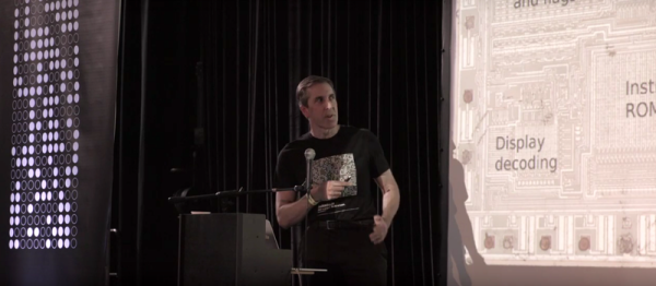
The folks at Zeptobars are on a roll, sometimes looking deep inside historic chips and at others exposing fake devices for our benefit. Behind all of those amazing die shots are hundreds of hours of hard work. [Mikhail] from Zeptobars recently tipped us off on the phenomenal work done by engineer [Vslav] who spent over 1000 hours reverse engineering the Soviet KR580VM80A – one of the most popular micro-controllers of the era and a direct clone of the i8080.

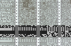
But before [Vslav] could get down to creating the schematic and Verilog model, the chip needed to be de-capped and etched. As they etched down, they created a series of high resolution images of the die. At the end of that process, they were able to determine that the chip had exactly 4758 transistors (contrary to rumors of 6000 or 4500). With the images done, they were able to annotate the various parts of the die, create a Verilog model and the schematic. A tough compatibility test confirmed the veracity of their Verilog model. All of the source data is available via a (CC-BY-3.0) license from their website. If this looks interesting, do check out some of their work that we have featured earlier like comparing real and fake Nordic dies and amazing descriptions of how they figure out the workings of these decapped chips. If this is too deep for you check out the slightly simpler but equally awesome process of delayering PCBs.

Deconstructing PCBs

The surest way to reverse engineer a circuit is to look at all the components, all the traces between these components, and clone the entire thing. Take a look at a PCB some time, and you’ll quickly see a problem with this plan: there’s soldermask hiding all the traces, vias are underneath components, and replicating a board from a single example isn’t exactly easy. That’s alright, because [Joe Grand] is here to tell you how to deconstruct PCBs one layer at a time.

Most of this work was originally presented at DEFCON last August, but yesterday [Joe] put up a series of YouTube videos demonstrating different techniques for removing soldermask, delayering multi-layer boards, and using non-destructive imaging to examine internal layers.

If you’re dealing with a two-layer board, the most you’ll have to do is remove the soldermask. This can be done with techniques ranging from a fiberglass scratch brush, to laser ablation, to a dremel flapwheel. By far the most impressive and effective ways to take the solder mask off of PCBs is the way the pros do it: chemically. A bath in Magnastrip 500 or Ristoff C-8 results in perfectly stripped boards and a room full of noxious chemicals. It makes sense; this is what PCB houses use when they need to remove solder mask during the fabrication process.

Removing a solder mask will get you the layout of a two-layer board, but if you’re looking at deconstructing multi-layer boards, you’ll have to delaminate the entire board stack to get a look at the interior copper layers. By far the most impressive way of doing this is with a machine that can only be described as gently violent, but passive, imaging techniques such as X-rays, CT scanners and other sufficiently advanced technology will also do the trick. Acoustic microscopy, or  Acoustic Micro Imaging, was, however, unsuccessful. It does look cool, though.

Thanks [Morris] for the tip.

Continue reading “Deconstructing PCBs”

Reverse Engineering Wireless Temperature Probes

[bhunting] lives right up against the Rockies, and for a while he’s wanted to measure the temperature variations against the inside of his house against the temperature swings outside. The sensible way to do this would be to put a few wireless temperature-logging probes around the house, and log all that data with a computer. A temperature sensor, microcontroller, wireless module, battery, case, and miscellaneous parts meant each node in the sensor grid would cost about $10. The other day, [bhunting] came across the exact same thing in the clearance bin of Walmart – $10 for a wireless temperature sensor, and the only thing he would have to do is reverse engineer the protocol.

These wireless temperature sensors are exactly what you would expect for a cheap piece of Chinese electronics found in the clearance bin at Walmart. There’s a small radio operating at 433MHz, a temperature sensor, and a microcontroller under a blob of epoxy. The microcontroller and transmitter board in the temperature sensor were only attached by a ribbon cable, and each of the lines were labeled. After finding power and ground, [bhunting] took a scope to the wires that provided the data to the radio and took a look at it with a logic analyzer.

After a bit of work, [bhunting] was able to figure out how the temperature sensor sent data back to the base station, and with a bit of surgery to one of these base stations, he had a way to read the temperature data with an Arduino. From there, it’s just a data logging problem that’s easily solved with Excel, and [bhunting] has exactly what he originally wanted, thanks to a find in the Walmart clearance bin.

Using MATLAB And SDR To Reverse Engineer 433MHz Messages

Hackers everywhere are having a lot of fun with SDR – as is obvious from the amount of related posts here on Hackaday. And why not, the hardware is cheap and easily available. There are all kinds of software tools you can use to dig in and explore, such as SDR# , Audacity, HDSDR and so on. [illias] has been following SDR projects for a while, which piqued his interest enough for him to start playing with it. He didn’t have any real project in mind so he focused on studying the methodology and the tools available for analyzing 433MHz RF transmission. He describes the process of using MATLAB to recover the transmissions being received by the SDR

He started off by studying the existing tools available to uncover the details of the protocol. The test rig uses an Arduino UNO with the rc-switch library to transmit via a common and inexpensive 433MHz module. SDR# is used to record the transmissions and Audacity allows [illias] to visualize the resulting .wav files. But the really interesting part is where he documents the signal analysis using MATLAB.

He used the RTL-SDR package in conjunction with the Communications System Toolbox to perform spectrum analysis, noise filtering and envelope extraction. MATLAB may not be the easiest to work with, nor the cheapest, but its powerful features and the fact that it can easily read data coming from the SDR makes it an interesting tool. For the full skinny on what this SDR thing is all about, check out Why you should care about Software Defined Radio.