Somewhere between the HF projects many of us have worked on, and the visible light spectrum lies the UHF, EHF, SHF, and THF. That’s Ultra, Extremely, Super, and Tremendously High Frequency for those who aren’t in the know. All of them involve frequencies in the gigahertz and terahertz range. While modern computers have made gigahertz a household term, actually working with signals in the gigahertz frequency range is still a daunting prospect. There have always been an elite group of hackers, makers, and engineers who tinker with projects using GHz frequencies. This week’s Hacklet is about some of the best GHz projects on Hackaday.io!
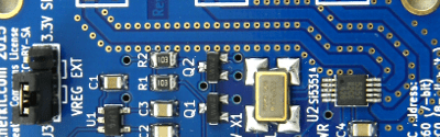
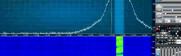
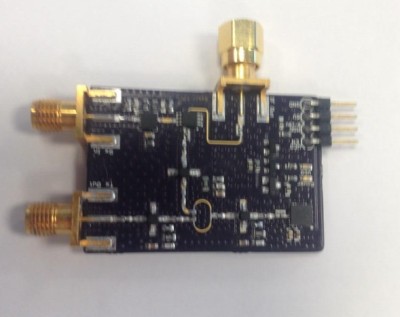 We start with [Luke Weston] and Simple, low-cost FMCW radar. For years people like Hackaday’s own [Gregory L. Charvat] have been building simplified radar systems and documenting them for the rest of us. [Luke’s] goal is to make radar systems like this even more accessible for the average hacker. He’s put all the specialized parts on one board. Rather than large Mini Circuits modules, [Luke] went with Hittite microwave parts in chip scale packages. Modulation comes from a Microchip MCP4921 mixed signal DAC. The system works, and has demonstrated transmission and reception 5 GHz to 6 GHz bands. [Luke] has even demonstrated detection of objects at close range using a scope.