Heart rate sensors available for DIY use employ photoplethysmography which illuminates the skin and measures changes in light absorption. These sensors are cheap, however, the circuitry required to interface them to other devices is not. [Petteri Hyvärinen] is successfully investigating the use of capacitive touchscreens for heart rate sensing among other applications.
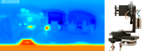
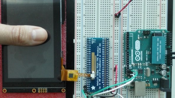
The capacitive sensor layer on modern-day devices has a grid of elements to detect touch. Typically there is an interfacing IC that translates the detected touches into filtered digital numbers that can be used by higher level applications. [optisimon] first figured out a way to obtain the raw data from a touch screen. [Petteri Hyvärinen] takes the next step by using a Python script to detect time variations in the data obtained. The refresh rate of the FT5x06 interface is adequate and the data is sent via an Arduino in 35-second chunks to the PC over a UART. The variations in the signal are very small, however, by averaging and then using the autocorrelation function, the signal was positively identified as a pulse.
A number of applications could benefit from this technique if the result can be replicated on other devices. Older devices could possibly be recycled to become low-cost medical equipment at a fraction of the cost. There is also the IoT side of things where the heart-rate response to media such as news, social media and videos could be used to classify content.
Check out our take on the original hack for capacitive touch imaging as well as using a piezoelectric sensor for the same application.