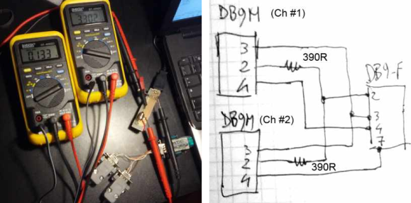
It’s pretty common to have at least a couple of meters around to measure different values of a circuit at the same time. Where [Emilio P.G. Ficara] ran into a problem was logging the data from both at once. These Fluke meters have a serial-out, but his computer only has a single serial-in port. He cracked open one of the meters and figured out how to log data from both at the same time.
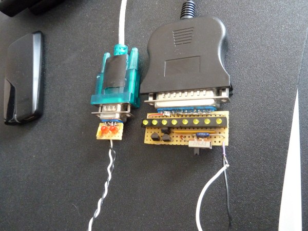
A lot of folks would look to a microcontroller to solve this problem. You use the chip to pull from each meter simultaneously and report back to a computer (or just dump the values onto an SD card). But this solution is a simple mechanical connector and a bit of creative programming. The way the serial output is set up on these meters they won’t interfere with each other as long as they’re read one at a time. [Emilio] wired them up as seen above, using his own software to manage the pins of the serial port. The example output he posted shows readings from the meters taken within about a tenth of second from each other. That should be good enough for most applications.