Modern operating systems insulate us — as programmers, especially — from so much work. Depending on how far back you go, programmers had to manage their own fonts, their own allocation space on mass storage, or even their own memory allotments. Every year, though, it seems like things get easier and easier. So why is it so annoying to open a simple serial port? It isn’t hard, of course, but on every operating system it seems to be painful — probably in an attempt to be flexible. And it is even worse if you want portability. I needed to write some C code that read data from an FPGA’s embedded logic analyzer, and I was annoyed at having to write yet more serial port code. I have my own shim library, but it isn’t well tested and isn’t all that flexible — it does what I need, but I wanted something better. What I wound up with the serial library from Sigrok. You know Sigrok? The logic analyzer software.
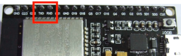
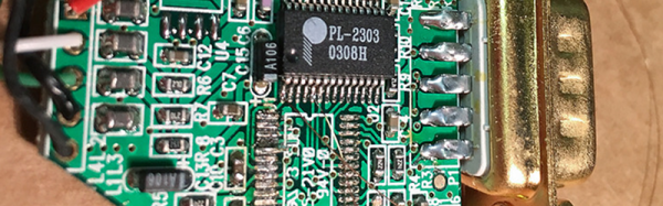
 You might counter that the serial port is old hat, so no one wants to support it with modern systems. While the physical serial port might be on life support, there’s no shortage of equipment that connects via USB that appears to be a serial port. So while I was talking to an FTDI chip on an FPGA board, you could just as well be talking to an Arduino or a USB voltmeter or anything.
I guess the Sigrok developers had the same problem I did and they took the time to write a nice API and port it to major platforms. Although Sigrok uses it, they maintain it as a separate project and it was just what I needed. Sort of. I say sort of because the version installed with Ubuntu was old and I needed some features on the newest release, but — as usual — the Internet came to the rescue. A quick Git command, and four lines of build instructions and we were ready to go.