A DIY Vacuum Pickup Tool For $75

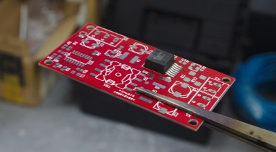
If you’re assembling prototypes of SMD boards on your own, placing the parts accurately can be a pain. Of course, it’d be nice to have a full pick and place machine, but those are rather expensive and time consuming to set up, especially for a small run of boards. Instead, a vacuum pickup tool can help you place the parts quickly and accurately by hand.

The folks over at Ohmnilabs have put together their own DIY pickup tool for about $75, and it’s become part of their in-house prototyping process. They grew tired of placing components with tweezers, which require you to remove parts from the tape before lifting them, and have a tendency to flip parts over at the worst time.

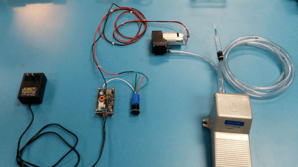
The build consists of a couple parts that can be bought from Amazon. An electric vacuum pump does the sucking, and the vacuum level is regulated with an adjustable buck converter. A solid foot switch keeps your hands free, and syringe tips are used to pick the parts up.

This looks like a simple afternoon build, but if you’re prototyping, it could save you tons of time. To see it in action, check out the video after the break.

Continue reading “A DIY Vacuum Pickup Tool For $75”

Hackaday Links Column Banner

Hackaday Links: October 23, 2016

It’s the Hack ‘O Lantern edition! First up, Slic3r is about to get awesome. Second, Halloween is just around the corner, and that means a few Hackaday-branded pumpkins are already carved. Here’s a few of them, from [Mike] and [yeltrow]:

The latest edition of PoC||GTFO has been released. Holds Stones From The Ivory Tower, But Only As Ballast (PDF and steganography warning). This edition has a reverse engineering of Atari’s Star Raiders, [Micah Elisabeth Scott]’s recent efforts on USB glitching and Wacom tablets, info on the LoRa PHY, and other good stuff. Thanks go to Pastor Manul Laphroaig.

Oh cool, we can be outraged about something. The Freetronics Experimenters Kit is a neat little Arduino-based ‘Getting Started In Microcontrollers’ kit. This kit was sold by Jaycar. Recently, Jaycar ripped off the kit and sold it under the Duiniotech name. The box was copied, the instruction manual was copied, and there’s a lot of IP being violated here. Can Freetronix do anything? Legally, yes, but it’s not worth it.

[Oscar] broke his phone, but it still works great as an SMD soldering camera/microscope thing.

Pobody’s Nerfect in Australia so here’s a 3D printed didgeridoo. What’s a didgeridoo? It’s an ancient instrument only slightly less annoying than bagpipes. It’s just a tube, really, and easily manufactured on any 3D printer. The real trick is the technique that requires circular breathing. That’s a little harder to master than throwing some Gcode at a printer.

[Chris Downing] is the master of mashed up, condensed, and handheld game consoles. His latest is another N64 portable, and it’s a masterpiece. It incorporates full multiplayer capability, uses an HDMI connector for charging and to connect the external breakout box/battery, and has RCA output for full-size TV gameplay. Of note is the breakout board for the custom N64 chip that puts pads for the memory card and a controller on a tiny board.

Design And Hacking Drilldown: SuperCon Badge

One can imagine a political or business conference without an interactive badge — but not a hacker conference. Does this make the case for hackers being a special breed of people, always having something creative to show for their work? Yes, I think it does.

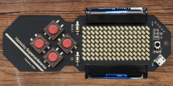
Following the Hackaday Belgrade conference in April of this year, we met at the Supplyframe offices to discuss the badge for the Hackaday SuperConference that will happen in Pasadena on 5+6th of November. The Belgrade conference badge (which was fully documented if you’re curious) was surprisingly popular, and I was asked to design the new one as well.

I was prepared to come up with something completely new, but [Mike Szczys] suggested keeping with the same basic concept for the project: “No reason to change anything, we have a badge that works”. To which I responded: “Well, the next one will also work”. But then I realized that “works” does not stand for “being functional”. The key is that it was embraced by visitors who played with it, coded on it, and solved a crypto challenge with it.

The World Doesn’t Have Enough LEDs

led-modules-versus-smdFast forward six months — here are the modifications made to the basic concept. First, the existing LED matrix, which was composed of two compact 8×8 blocks, was replaced by 128 discrete SMD LEDs. It was a much needed change to help scale down the dimensions and clunkiness, but also to avoid another painful experience of trying to purchase and have the matrix displays shipped, which seriously threatened the production of the previous badge.

It’s a long story which I discussed in my Belgrade talk — it turned out we did not manage to get enough common anode (CA) displays from all distributors in the whole world. We had a plan B, which also fizzled, leaving us with the plan C which actually included two “C”s: Common Cathode. We cleaned up all the supplies at five distributors, and managed to get 122 CA red, 340 CC red and 78 CA green displays (enough for only 270 badges) — the entire world supply. After that, you couldn’t get any 38 mm Kingbright’s display for months! The only problem was that there were two different versions of PCBs, one for CA and the other for CC displays, but luckily only one version of software, as it could autodetect the display type.
accelerometer-on-the-boardMotion and Expansion

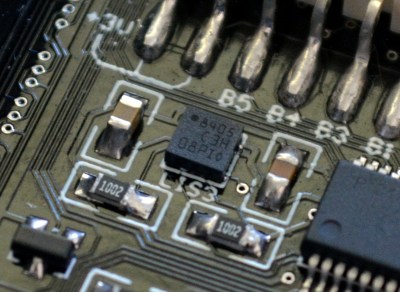
So, what else was new in the concept? In the Belgrade version, the badge supported an accelerometer module and included an unpopulated footprint in case you decided to install it, but now the badge has the MEMS chip LIS3 as an integral part. There are nine pads (with five I/O ports, driven directly from the MCU) to which you can add a 9-pin expansion connector. There will be a number of these connectors at the Design Lab, so that anyone can expand their badge for their convenience, on the spot.

The Visual Design

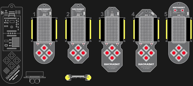
The biggest change was in the visual design. What we came up with ended up being a fair bit smaller, lighter, with a more convenient shape, and less than half the thickness of the previous one. After we had scrapped quite a few ideas during the development process (including stylized skull, frog, etc), we were left with a couple of options which you can see on the image below. The wireframe drawing on the left hand side is the Belgrade badge, shown here for a size comparison. At this point the locale and date of the conference weren’t yet definitive, which is why you see San Francisco written on the images.
design-options-2016-supercon-badge

Design number 4 prevailed, so the PCB layout could begin. I don’t like autorouted PCBs, so I was in for quite a rough time trying to solve the routing manually having only 2 layers on the board at my disposal.

Routing a Compact LED Matrix

The LED matrix is so dense that there was virtually no room on the LED layer, so most of the tracks on the component layer had to be routed as if it was a single layer PCB. To make matters worse, the LED layer is routed as a matrix, with a bunch of horizontal and vertical tracks, otherwise a good reason to use a 4-layer PCB. To stay inside the budget, everything had to be placed on 2 layers, and that’s why the final result seems so confusing at the populated area between batteries:

Continue reading “Design And Hacking Drilldown: SuperCon Badge”

[NE555]’s SMD Prototyping Is A Work Of Art

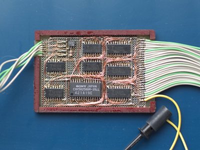
ne555_20yearsold
One of [NE555]’s boards from the 90s.
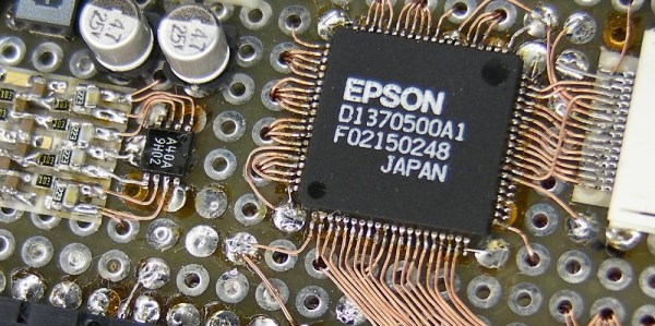
Over on twitter [NE555] has been posting beautiful SMD prototypes.

Back in the 90s when surface mount components gained widespread adoption, the quick and cheap PCB prototyping services of today were unavailable. This led many to develop their own approaches. In Japan a particularly novel and beautiful approach was, and still is, somewhat popular. [NE555]’s work is a excellent example of this technique using a fine enameled wire (you can find this on eBay as “magnet wire”), wirewrap board, and careful hand soldering. [NE555] has made a great video on the process (which you can watch below).

Continue reading “[NE555]’s SMD Prototyping Is A Work Of Art”

Blowtorch SMD Reflow

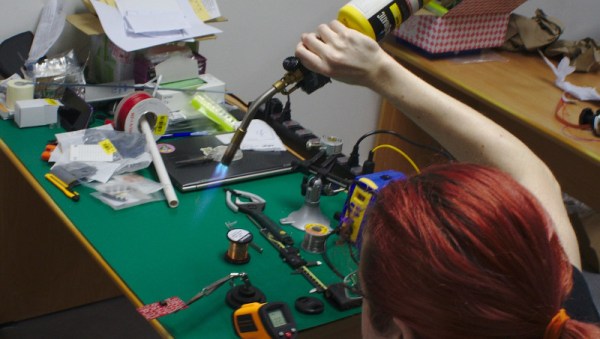
result[whitequark] has been experimenting with a blowtorch for SMD reflow. Having just moved 8,000 km [whitequark] was stuck without any of the usual reflow tools. They did however have a blowtorch handy, and gave it a go.

When [whitequark] mentioned attempts on Twitter, we figured the results would mostly involve charred PCBs, smoke-filled rooms, and a possible trip to the local hospital. But [whitequark] is more sensible than we are, and by carefully monitoring the temperature and gauging the distance was able to get pretty decent results.

[whitequark]’s made a couple of further attempts and has had varying results. Overall, I’m not sure it’s a technique that I’m interested in trying myself, but it goes to show that in a pinch, a hacker will always find a creative way to get the job done.

Almost Fail Of The Week: Doing Surface Mount Reflow Wrong In Every Possible Way And Still Succeeding

Sometimes the best way to learn is from the success of others. Sometimes failure is the best teacher. In this case we are learning from [Tim Trzepacz]’s successive failures in his attempt to solder one board to another using a reflow oven. They somehow cancelled each other out, and he ended up with a working board. For those of you who have used a reflow oven, there will be eye rolling.

[Tim]’s first mistake was to use regular solder instead of paste. We can see how he got there logically; if you hand solder an SMD you melt solder onto the pads first to make it easier. However, the result was that he had two boards that wouldn’t sit flat on each other thanks to the globs of solder on the pads.

Not to be deterred, he laid the boards on top of each other and warmed up the oven to a toasty 650 degrees. Well, not quite. The dang oven didn’t turn to eleven, so he figured 500 would probably work too. Missing the hint entirely, he let his board bake in a nearly 1000F oven until he noticed some smoke which, he intuitively knew, definitely shouldn’t be happening.

The board was blackening, the solder mask was literally bubbling off the substrate, people were coming over to see the show, and he decided success was still possible. He clamped the heated boards together with a binder clip until they cooled. Someone gave him a lesson on reflow, presumably listened to through reddening ears.

Ashamed and defeated, he went home. However, there was a question in his mind. Sure it looks bad, but is it possible that the board actually works? After a quick test, the answer was yes. It loaded some code and an time later he was happily hacking away. Go figure.

One SMT Breakout To Rule Them All

You need to use surface-mount technology (SMT) parts in your design. But you also need to prototype. How to fit those little buggers into your breadboard?

[Simon] came up with a general-purpose SMT-to-breadboard solution. Now, there are already myriad adapter boards for the many-pin devices: SSOP-to-DIP adapters and so on. But what do you do when you just need to work that tiny SOT223 voltage regulator into a breadboarded circuit?

[Simon]’s solution fills that gap with one breadboardable design to handle all of your small-pin-count part needs. It accommodates SOT223, SOT323, and SOT23 three-pin parts like transistors or voltage regulators, and also has pads for all of the common two-terminal parts like resistors and capacitors from 0402 on up to 1206. You could build up a full voltage regulator circuit on one of these things. He’s even included some whitespace on the back for your notes.

SMT parts aren’t even the future any more. And with the right procedure, they’re not hard to hand-assemble. So the next time you have some extra space in a PCB order, toss in a couple of [Simon]’s breakouts and you’ll be ready for your next breadboarding session.