Photovoltaic Cells In LTSpice

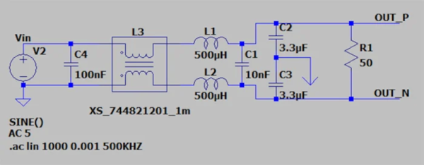
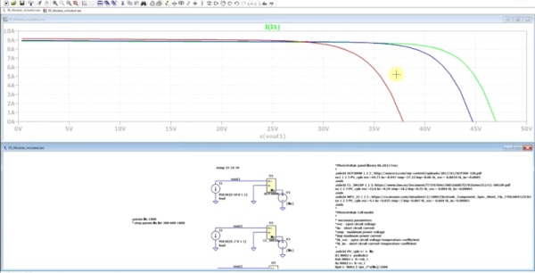
We like to build things using real parts. But we do think the more you can model using tools like LTSpice, the less time you can spend going down dead ends. If you need to model a common component like a resistor or even an active device, most simulators have great models and you can tweak them to have realistic parasitic effects. But what if the component you want isn’t in the library or doesn’t have the fidelity you want? [FesZ] wanted to model photovoltaic cells and had to build his own model. The resulting two videos are well worth watching.

Building your own models in Spice isn’t necessarily very difficult. However, knowing exactly what to add to model different real-world effects can be challenging. The videos do a good job of showing how to mutate a simple diode into one that produces current when exposed to light.

Continue reading “Photovoltaic Cells In LTSpice”

LTSpice Tips And A Long Tutorial

We always enjoy videos from [FesZ], so when we saw his latest about tips and tricks for LTSpice, we decided to put the 20 minutes in to watch it. But we noticed in the text that he has an entire series of video tutorials about LTSpice and that this is actually episode 30. So there’s plenty to watch.

Like any tips and tricks video, you might know some of them and you may not care about some of them — for example, the first one talks about setting the colors which is a highly personal preference.  But it is a good bet you’ll find something to like in the video.

Continue reading “LTSpice Tips And A Long Tutorial”

Class A Amplifiers, Virtually

If you didn’t know better, you might think the phrase “class A amplifier” was a marketing term to help sell amplifiers. But it is, of course, actually a technical description of an amplifier that doesn’t distort the input waveform because it doesn’t depend on multiple elements to handle different areas of the input waveform. Want to know more? [FesZ] has a new video covering the basics of class A amplifiers including some great simulations. You can see the video below.

A class A amplifier uses a transistor that is always biased on. It never saturates or switches off. This is good for linearity, but not always the best for efficiency so there are other classes of amplifiers, too. However, for many applications, class A is the most common configuration.

There are a number of trade-offs involved with each type of amplifier and [FesZ] covers them in detail. But the real interesting part is the simulations in Spice. Sure, you can build the circuits and look at everything with a meter or scope, but using Spice is much handier.

There is a second video upcoming. We hope he covers other amplifier types too, as you really do want to understand the differences when you need to design something. If you want more Spice stuff, check out some of our previous posts. If for some reason, you don’t like LTSpice, there’s always Micro-Cap 12.

Continue reading “Class A Amplifiers, Virtually”

Custom Components In LTSpice

If you enjoy simulating circuits, you’ve probably used LTSpice. The program has a lot of powerful features we tend to not use, including the ability to make custom components that are quite complex. To illustrate how it works, [asa pro] builds a potentiometer component that is not only a good illustration but also a useful component.

The component is, of course, just two resistors. However, using parameters, the component gets two values, a total resistance and a percentage. Then the actual resistance values adjust themselves.

Continue reading “Custom Components In LTSpice”

Circuit Impedance Calculations Without Cumbersome Simulations

Using circuit simulating software like SPICE can be a powerful tool for modeling the behavior of a circuit in the real world. On the other hand, it’s not always necessary to have all of the features of SPICE available all the time, and these programs tend to be quite expensive as well. To that end, [Wes Hileman] noticed an opportunity for a specific, quick method for performing impedance calculations using python without bulky, expensive software and came up with a program which he calls fastZ.

The software works on any network of passive components (resistors, capacitors, and inductors) and the user can specify parallel and series connections using special operators. Not only can the program calculate the combined impedance but it can perform frequency analysis at a specified frequency or graph the frequency response over a wide range of frequencies. It’s also running in python which makes it as simple as importing any other python package, and is also easy to implement in any other python program compared to building a simulation and hoping for the best.

If you find yourself regularly drawing Bode plots or trying to cobble together a circuit simulation to work with your python code, this sort of solution is a great way to save a lot of headache. It is possible to get the a piece of software like SPICE to to work together with other python programs though, often with some pretty interesting results.

Circuit VR: Squaring With Schmitt Triggers

In the fantasy world of schematic diagrams, wires have no resistance and square waves have infinitely sharp rise times. The real world, of course, is much crueler. There are many things you can use to help tame the wild analog world into the digital realm. Switches need debouncing, signals need limiting, and you might even need a filter. One of the basic elements you might use is a Schmitt trigger. In

In this installment of Circuit VR, I’m looking inside practical circuits by building Schmitt triggers in the Falstad circuit simulator. You can click the links and get to a live simulation of the circuit so you can do your own experiments and virtual measurements.

Why Schmitt Triggers?

You usually use a Schmitt trigger to convert a noisy signal into a clean square digital logic level. Any sort of logic gate has a threshold. For a 5V part, the threshold might be that anything under 2.5V is a zero and at 2.5V or above, the signal counts as a one. Some logic families define other thresholds and may have areas where the signal is undefined, possibly causing unpredictable outputs.

There are myriad problems with the threshold, of course. Two parts might not have exactly the same threshold. The threshold might vary a bit for temperature or other factors. For parts with no forbidden zone, what happens if the voltage is right at the edge of the threshold?

Continue reading “Circuit VR: Squaring With Schmitt Triggers”

Make Some Noise Or Simulate It, At Least

Noise is a fact of life, especially in electronic circuits. But on our paper schematics and just as often our simulations, there is no noise. If you are blinking an LED on a breadboard, you probably don’t care. But if you are working on something meatier, handling electrical noise gracefully is important and simulation can help you. [Ignacio de Mendizábal] has a great piece on simulating EMC filters using LTSpice that can get you started.

There are many ways of classifying noise and [Ignacio] starts with common-mode versus differential noise, where common-mode is noise with current flowing in the same direction without regard to the circuit’s normal operation, and differential noise having currents that flow in the opposite direction of normal current flow.

Continue reading “Make Some Noise Or Simulate It, At Least”