It is no secret that we like slide rules around the Hackaday bunker, and among our favorites are the cylindrical slide rules. [Chris Staecker] likes them, too, and recently even 3D printed a version. But spurred by comments on his video, he decided to try something that might be unique: a helical slide rule. You can see how it works in the video below.
With a conventional slide rule, the scale is rotated around a cylinder so that it is the same length as a much longer linear scale. However, this new slide rule bends the entire rule around a cylinder and allows the slide to move, just like a conventional slide rule. If you have a 3D printer, you can make your own.
Back in the early 1900s, before calculators lived in our pockets, crunching numbers was painstaking work. Adding machines existed, but they weren’t exactly convenient nor cheap. Enter Wilken Wilkenson and his Maximal Multi-Divi, a massive multiplication and division table that turned math into an industrialized process. Originally published in Sweden in the 1910’s, and refined over decades, his book was more than a reference. It was a modular calculating instrument, optimized for speed and efficiency. In this video, [Chris Staecker] tells all about this fascinating relic.
What makes the Multi-Divi special isn’t just its sheer size – handling up to 9995 × 995 multiplications – but its clever design. Wilkenson formatted the book like a machine, with modular sections that could be swapped out for different models. If you needed an expanded range, you could just swap in an extra 200 pages. To sell it internationally, just replace the insert – no translation needed. The book itself contains zero words, only numbers. Even the marketing pushed this as a serious calculating device, rather than just another dusty math bible.
While pinwheel machines and comptometers were available at the time, they required training and upkeep. The Multi-Divi, in contrast, required zero learning curve – just look up the numbers for instant result. And it wasn’t just multiplication: the book also handled division in reverse, plus compound interest, square roots, and even amortizations. Wilkenson effectively created a pre-digital computing tool, a kind of pocket calculator on steroids (if pockets were the size of briefcases).
Of course, no self-respecting hacker would take claims of ‘the greatest invention ever’ at face value. Wilkenson’s marketing, while grandiose, wasn’t entirely wrong – the Multi-Divi outpaced mechanical calculators in speed tests. And if you’re feeling adventurous, [Chris] has scanned the entire book, so you can try it yourself.
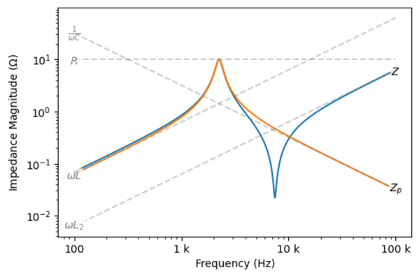
Using circuit simulating software like SPICE can be a powerful tool for modeling the behavior of a circuit in the real world. On the other hand, it’s not always necessary to have all of the features of SPICE available all the time, and these programs tend to be quite expensive as well. To that end, [Wes Hileman] noticed an opportunity for a specific, quick method for performing impedance calculations using python without bulky, expensive software and came up with a program which he calls fastZ.
The software works on any network of passive components (resistors, capacitors, and inductors) and the user can specify parallel and series connections using special operators. Not only can the program calculate the combined impedance but it can perform frequency analysis at a specified frequency or graph the frequency response over a wide range of frequencies. It’s also running in python which makes it as simple as importing any other python package, and is also easy to implement in any other python program compared to building a simulation and hoping for the best.
If you find yourself regularly drawing Bode plots or trying to cobble together a circuit simulation to work with your python code, this sort of solution is a great way to save a lot of headache. It is possible to get the a piece of software like SPICE to to work together with other python programs though, often with some pretty interesting results.
I was reading Sonya Vasquez’s marvelous piece on the capstan equation this week. It’s a short, practical introduction to a single equation that, unless you’re doing something very strange, covers everything you need to know about friction when designing something with a rope or a cable that has to turn a corner or navigate a wiggle. Think of a bike cable or, in Sonya’s case, a moveable dragon-head Chomper. Turns out, there’s math for that! Continue reading “Run The Math, Or Try It Out?”→
Gravity can be a difficult thing to simulate effectively on a traditional CPU. The amount of calculation required increases exponentially with the number of particles in the simulation. This is an application perfect for parallel processing.
For their final project in ECE5760 at Cornell, [Mark Eiding] and [Brian Curless] decided to use an FPGA to rapidly process gravitational calculations. This allows them to simulate a thousand particles at up to 10 frames per second. With every particle having an attraction to every other, this works out to an astonishing 1 million inverse-square calculations per frame!
The team used an Altera DE2-115 development board to build the project. General operation is run by a Nios II processor, which handles the VGA display, loads initial conditions and controls memory. The FPGA is used as an accelerator for the gravity calculations, and lends the additional benefit of requiring less memory access operations as it runs all operations in parallel.
This project is a great example of how FPGAs can be used to create serious processing muscle for massively parallel tasks. Check out this great article on sorting with FPGAs that delves deeper into the subject. Video after the break.
Practically any combination of motor and gearbox can be mathematically arranged to fit all sorts of problems. You could lift a crane with a pager motor, it just might take a few hundred years. However, figuring out exactly what ratio you need can feel bit backwards the first time you have to do it.
A gear is nothing more than a clever way to make two circles rotate in concert with each other as if they were perfectly joined at their circumferences. Rather than relying on the friction between two rotating disks in contact, the designer instead relies on the strength of a gear tooth as the factor limiting the amount of torque that can be applied to the gear.
Everything is in gearing is neatly proportional. As long as your point of reference is correct, and some other stuff. Uh, it gets easier with practice.
Now as my physics professors taught me to do, let’s skip the semantics and spare ourselves some pedantics. Let us assume that all gears have a constant velocity when you’ve averaged it all out. Sure there is a perceptible difference between a perfect involute and a primitive lantern gear, but for the sake of discussion it doesn’t matter at all. Especially if you’re just going to 3D print the thing. Let’s say that they’re sitting on perfect bearings and friction isn’t a thing unless we make it so. Also we’ll go ahead and make them perfectly aligned, depthed, and toleranced.
Typically, a gearbox is used for two things. You have a smaller torque that you’d like to make into a bigger one or you have one rotational velocity that you’d like to exchange for another. Typically torque is represented with a capital or lowercase Tau (Ττ) and rotational velocity likes to have a lowercase omega (ω). It also doesn’t matter at all; it just makes your equations look cooler.
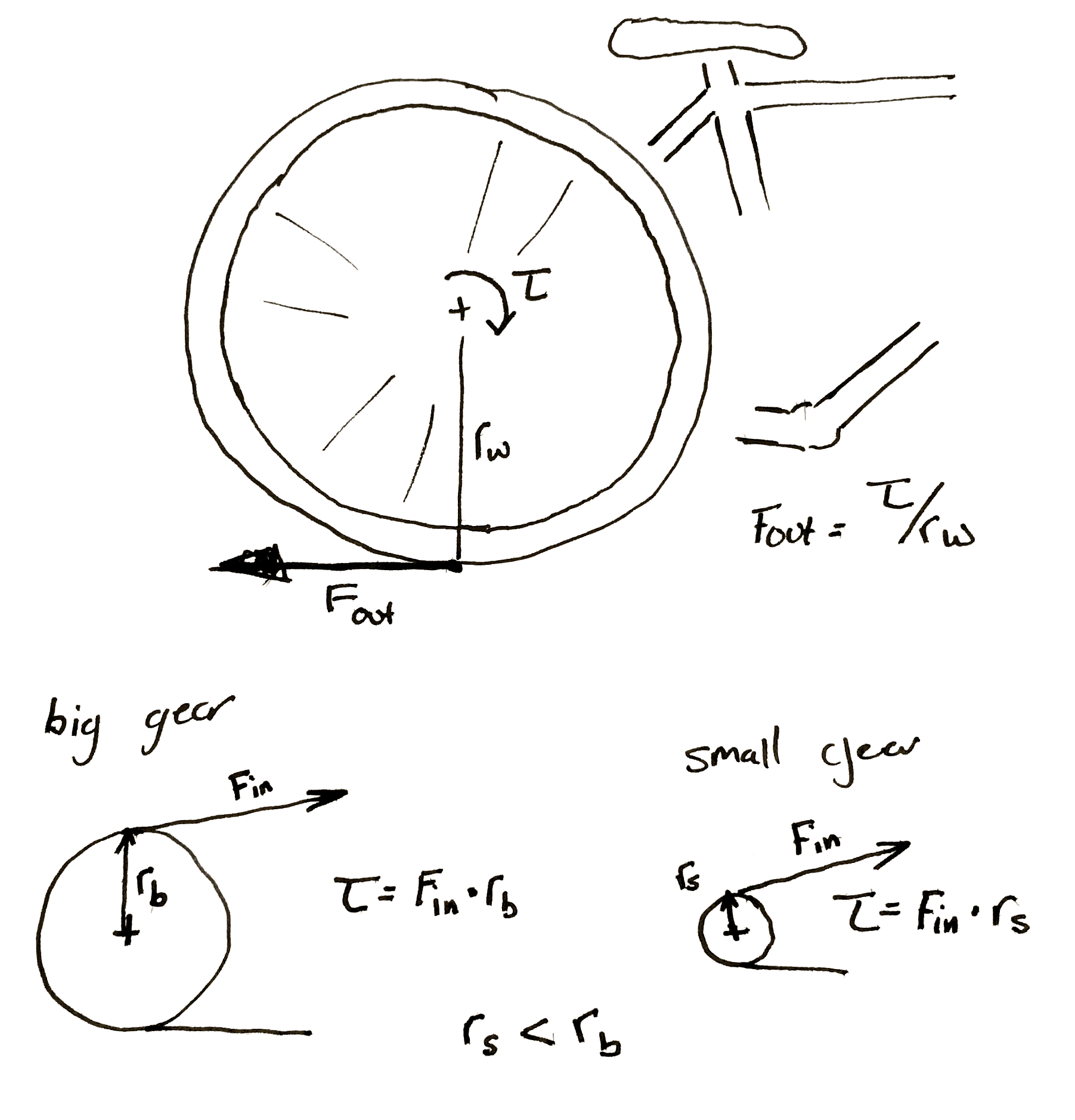
Now a lot of tutorials like to start with the idea of rolling a smaller circle against a bigger one. If the smaller circle is a third as large as the big one, it will take three rotations of the small circle to make the big one rotate twice. However, it is my opinion that thinking it in terms of the force applied allows a designer to think about the gearing more effectively.
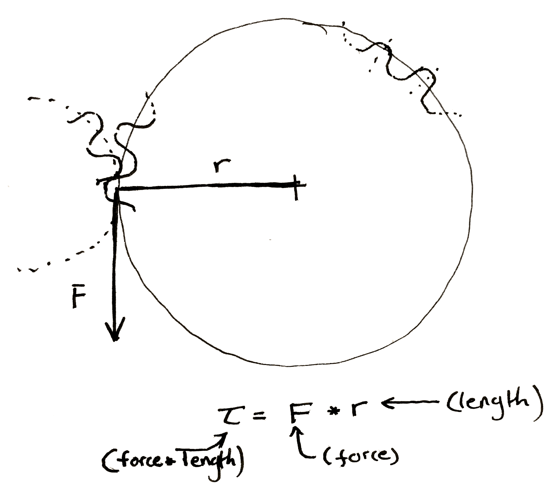
If the friction between the two surfaces of the circle is perfect, then any force applied tangentially to one of the circles will result in a perfectly perpendicular and equal force to the other circle at the point of contact between the two. Midway through writing the preceding sentence I began to understand why textbooks are so abstruse, so I also drew a picture. This results in two equations.
Now, when you have a force perpendicular to the line drawn to describe the radius, the equation for torque becomes really simple.
Multiply the length of the “lever arm”, “radius”, etc. by the force to get the preceding equations. Make sure to include the units.
You should end up force-unit * length-unit. Since I usually work in smaller gears I like to use N * mm. American websites typically use oz-in to rate motors. It is technically ozf-in (ounce-force), but the US customary system has a fetish for obtuseness.
We can make some observations. The smaller gear always sees less torque at its center. This initially seemed a bit counter-intuitive to me. If I’m using a cheater bar to turn a bolt the longer I make the bar the more torque I can put on the bolt. So if I touch the outside of a really large gear I should be seeing a ton of torque at the center of a small gear rotating along with it. However, as we mentioned before, any torque applied on the outside of the larger gear is seen equal and tangential on the smaller. It’s as if you’re touching the outside of the small gear. The torque has to be smaller.
This is why you have to pedal so much harder when the rear sprocket on a bicycle gets smaller. Each time you make the sprocket smaller you shrink the torque input into the wheel. If the perpendicular output where the wheel hits the ground is <input from the small gear> / <radius of the wheel> then it’s obvious why this happens.
Hopefully my diagram doesn’t win a prize for awfulness. Then again, an award is an award. Remember that the bicycle wheel and its input gear are rigidly attached to each other.
It’s also important to note that any time you increase the torque, the speed of the gears slow by the same proportion. If you need 60 N*m out of a motor that can give 20 N*m and you use a 3:1 gearbox to do it. If the motor previously ran at 30 rpm it’s now running at 10 rpm.
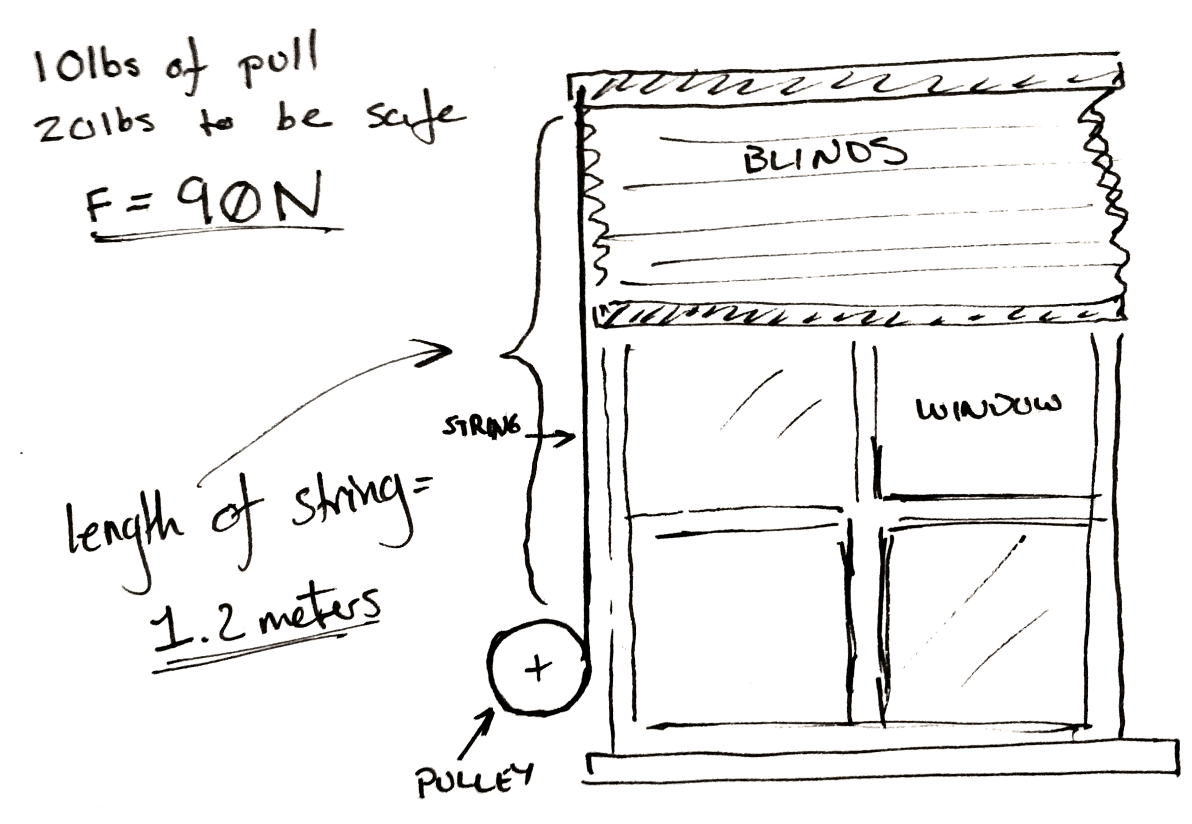
Let’s jump right into an example. Let’s say you want to make a device that automatically lifts your window blinds. You’ve got some junk and a 3D printer.
The problem set-up.
Now you’ve taken a spring scale and pulled until the shutter moves and you know you need 10 lbs. of pull to get the blinds to pull up. To make it easy on yourself you multiply this number by two so you know you need exactly 20 lbs of force to pull the curtain up. Then to make it really easy on yourself convert it all to Newtons. It’s approximately 90 N.
Now you don’t really care how fast the blinds pull up, but you go ahead and pull them up yourself. You get the feeling that the blinds won’t appreciate being lifted faster than the whole range in two seconds. You personally don’t care if takes ten seconds to, but you’d like it not to take too long.
You also measure the length of string pulled out to raise the blinds. It’s 1.2 meters.
A classic.
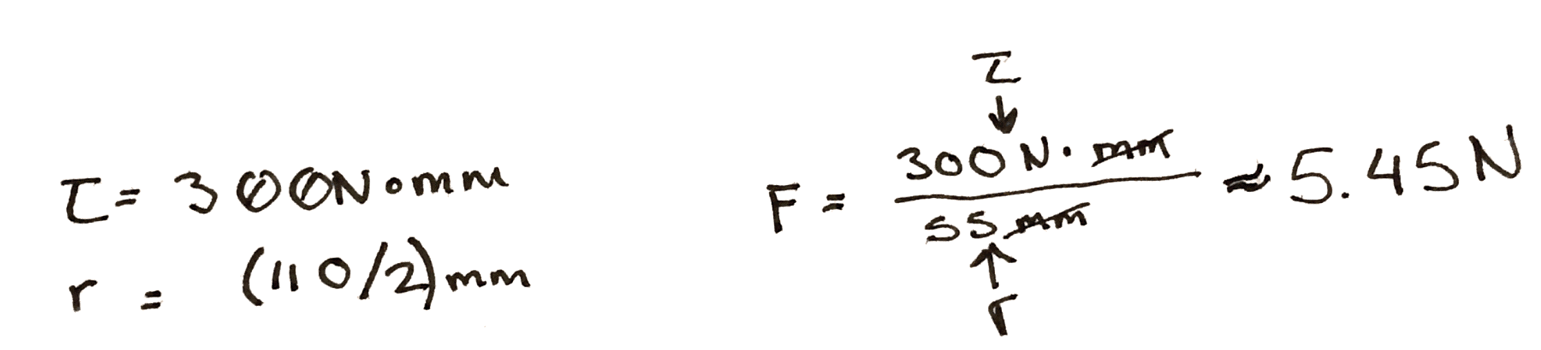
Lastly, you only have one spare power supply and a matching motor left in your entire laboratory after you followed the advice in a Hackaday article. Cursing the day the author was born, you sullenly write down the last specifications. You’ve got one of those cheap GM9 gear motors. 5 V, 66 rpm, and 300 N*mm. You damn him as you think fondly of your mountain of windshield washer motors and 80 lb server rack power supplies that you tossed out.
To start with, you do some experiments with a pulley. You arbitrarily pick, 3D print, and find that a 100 mm in diameter pulley seems to wind it up nicely by hand. By the end of the winding the outside diameter of the string is 110 mm. So you use the torque equations above. You find that at the end of the rotation, if you attach the motor directly, there is only 5.45 N of force being applied to the string. Not nearly enough.
Hrm..
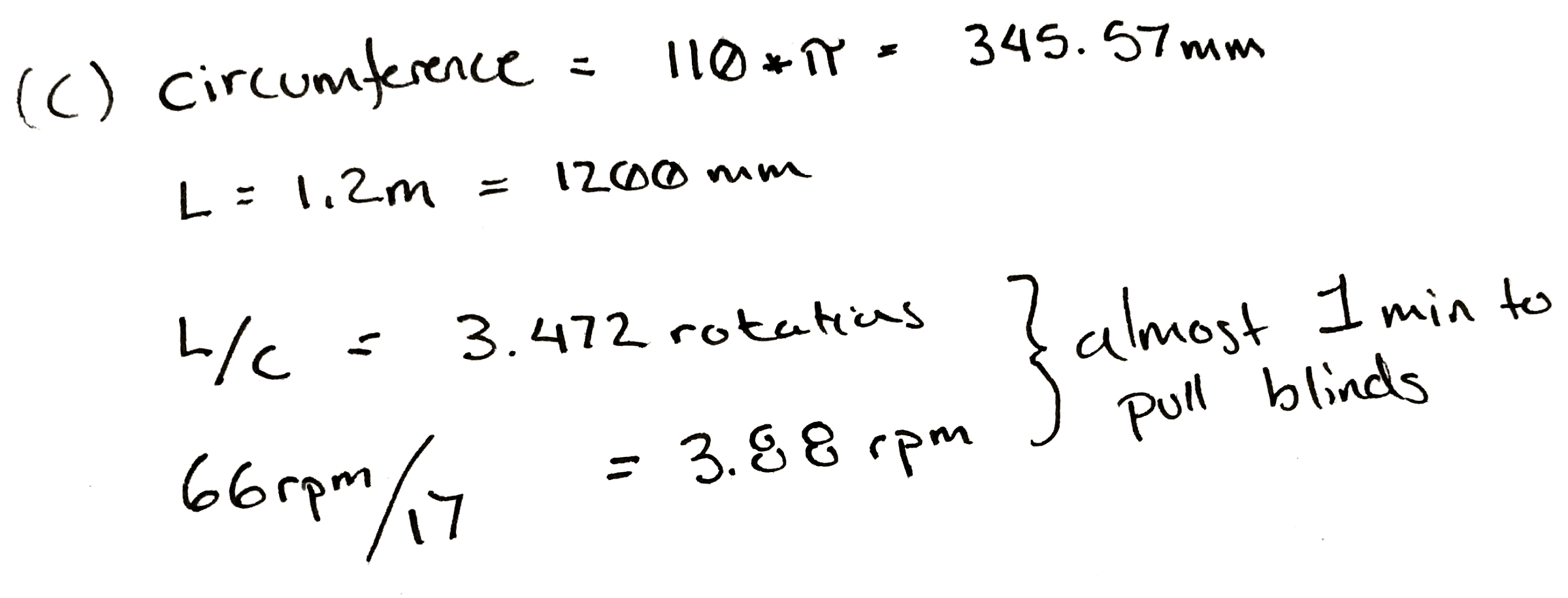
So, since you know everything is more or less proportional, you divide 90 N / 5.45 N, and arrive at an answer of 17. So, at a minimum for every turn of the pulley you need 17 turns of the motor to get the torque needed.
That would be okay, but it messes with our other specification. At a 17:1 ratio, it will take our 66 rpm motor pretty close to a minute to wind the blinds up.
Damn.
This is a moment for some pondering. Make a coffee. Maybe go write a relaxing comment to a Hackaday writer listing their various flaws, perceived and true, in excruciating detail.
What if you wound the string up on a closet rod? Those are only about 30 mm in diameter. You take a bit of rod and wind it up. It seems to work and since it’s wider the string only ends up adding 5 mm to the final diameter. You rework the calculation and find that in this case you only need a ratio of 6! Yes.
Now some of you who have done this before are likely gnashing your teeth, or more likely already down in the comments. Unfortunately it’s all proportional. While you only need a ratio of 6:1 now, nearly a third. You also need to rotate the pulley approximately three times as much to pull the same length of cord.
Sometimes you can’t win. In this case the only solution is to order a new motor. You look online for a bit and realize that one of the 12 V motors you threw away last week would work perfectly for this. You wouldn’t even need a gear box. You could attach it straight to the pulley. You look around your perfectly clean and orderly garage and feel empty.
However, just for fun you build a 6:1 gearbox anyway. It’s a hack after all.
Cover photo of the hilariously complicated Do Nothing Machine credit to the Joe Martin Foundation.