Video Review: STM32F0-Discovery Board

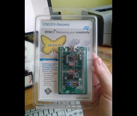
The STM32 Discovery boards are nothing new, we’ve looked at them several times. But the newest sibling in the line might be just the thing to make the leap from your steadfast 8-bit projects. We got our hands on it and recorded a video review.

The STM32F0-Discovery gives you a programmer and ARM Cortex-M0 chip all on one convenient board. The top portion is the ST-Link V2 programmer, and includes jumpers and a programming header which let it easily program off-board chips.

The included microcontroller is an STM32F051R8T6 which includes 64kb of program memory and 8kb of RAM. Coming in at $1.80-3.77 in single units and in a hand-solderable LQFP package this raises an eyebrow for our future projects. It has an 8 MHz internal oscillator with 6x PLL which means you can run at 48 MHz without an external crystal (check out [Kenneth Finnegan’s] PLL primer if you don’t know what this is).

The only thing holding us back is the development environment. ST provides everything you need if you’re on Windows, but we want a Linux friendly solution. We know other Discovery boards have worked under Linux thanks to this project. This uses the same ST-LINK V2 so it should work as well. If you want one of your own head over the ST page to see if they’re still giving away samples. There should be a button labeled “Register for your FREE KIT”.

Resizable ARM Dev Board; Just Take Some Off The Top

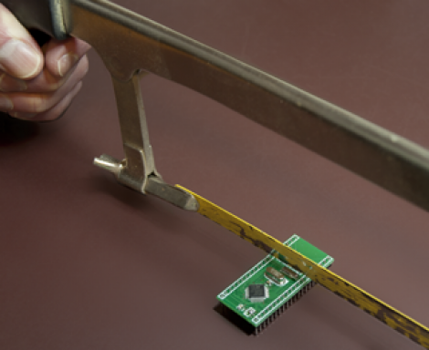
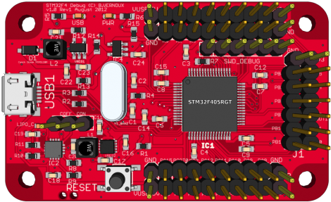
[Bob Alexander’s] most recent project is a hack saw resizable ARM breakout board. He wanted to start using more ARM microcontrollers in his projects and went for a breadboard friendly design. It uses a 40-pin dip package, but if you need the horsepower but not the I/O you can literally cut it down to size. We might recommend grabbing some tin snips, which can cut through a PCB like butter, but to each his own.

The board is based around an STM32 chip. You’ll find a crystal oscillator for the system clock, and a clock crystal if you need it. On the other side of the chip he included a footprint for a voltage regulator. This setup provides a remarkable range of input voltages, accepting from 2 to 3.6 volts without the regulator, and up to 16 volts if the regulator is present. He designed a package footprint that can be easily bridged if there’s no SMD part there. Just make sure you insulate that pad if you are using one with a conductor on the bottom. He explains this in detail in his writeup.

You’ll need a programmer to work with the board. He uses an STM32 Discovery Board for this but there are quite a few other options out there too.

Using A Touch Screen With An STM32 Microcontroller

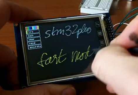
[Andy Brown] has been working on a series of tutorials revolving around the STM32 processor family. He’s using the STM32plus development board, with an STM32F1 ARM Cortex M3 processor to drive a couple of different full color graphic LCD screens. His latest installment shows how to read from the touch screen included with both displays.

After the break we’ve embedded the video from which this screenshot was taken. As an example, [Andy] has programmed a painting program to show off what the touchscreen overlay is capable of. It starts off with the calibration routine we’re all familiar with, then drops to this screen with a virtual control panel and blank canvas.

This hardware uses the Texas Instruments ADS7843 controller, which [Andy] says is extremely common and that several other manufacturers use the same communications protocols. He discusses how to communicate with the controller, and how to incorporate the data into your program. Included is an open source library which you can use in your own projects.

Continue reading “Using A Touch Screen With An STM32 Microcontroller”

Micromouse Wins 2011 Maze Race In Under 4 Seconds

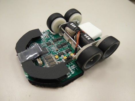
It’s off to the races once again with the Micomouse maze solving contest at the 2011 RoboGames. This is a picture of the winner, a bot called Min7 (main page) which was built by [Ng Beng Kiat]. Using four phototransistors and a flash sensor it managed to first map the contest maze, then speed run it in under four seconds. See both runs in videos after the break. He’s certainly got a leg up on the bots we saw last year. Min7 beats them both in time, and overall control during the speed run.

[Ng] mentions that this year is the first time he’s built a micromouse with four wheels instead of two. There’s a gyro on board which aids navigation by feeding the orientation data to the STM32 chip which controls the device. We took a moment to page through his past designs. It’s remarkable how they’ve evolved through the years. Continue reading “Micromouse Wins 2011 Maze Race In Under 4 Seconds”

ARM Programming Primer; Getting The USART Running

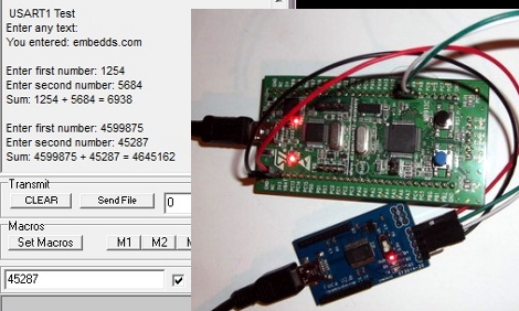
We find it interesting that PIC and AVR programming is very common in hobby electronics but ARM doesn’t have nearly the same foothold. This is partly because there’s a knowledge barrier involved with making the transition (the other part is probably the lack of DIP packaged chips). But if you’ve worked with 8-bit microcontrollers you can certainly make the jump into the 32-bit realm. Here’s a great opportunity to get your feet wet. This guide will show you how to get the USART on an STM32 Discovery Board working, which makes it easy to get feedback about what’s going on in your program.

One difference you’ll notice when moving to ARM microcontrollers is that there is almost always a library bundle available from the manufacturer which includes all of the functions you need for hardware control (USART, USB, Ethernet, ADC, etc.). That’s the case here, so simply including the USART library makes it a snap to finish the rest of the program. Once you hook up your communications hardware (an FTDI cable in this case) just use the library initialization functions, followed by the send and receive commands and you’ll be pushing messages to a computer terminal in no time.

If you’re trying to use the STM32 Discovery Board with a Linux box here’s a shove in the right direction.

How To Develop For STM32 Discovery Boards Using Linux

Some hard work has gone into making it possible to develop for the STM32 Discovery board using a Linux system. The board boasts an ARM Cortex-M3 processor, which can be programmed via the mini-USB port on the side. But the company only supports development through their IDE’s which don’t run natively on Linux. The stlink project aims to solve this, providing a toolchain, and making it possible to flash the microcontroller via the USB connection.

The github project linked above also includes a tutorial to get you started (pdf). In addition to a walk through on compiling the software packages, it includes a simple blink program that you can use to test out your hardware. GDB, the familiar open-source debugger, is used to flash the chip. This is a bare-bones tutorial so if you end up posting about your experiences using this toolchain with the Discovery boards we’d love to hear about it.

[Thanks Texane]

Only Losers Text Message On Cellphones – This Guy Carries His Own Teletype For That

Yes, that’s an SMS text messaging device. [Mdziewie] decided that texting on a regular cellphone was too boring and decided to build himself an old-school SMS gateway. Here’s a translated link but the formatting of the forum post gets screwed up with the machine translation.

The device he’s using is an ASR-33 Teletype machine, which was introduced to the market in 1963. It is connected to a GSM modem via an ARM microcontroller, the STM32F103. This chip, along with a few electronic components, let [Mdziewie] design an interface that doesn’t require alteration to the ancient hardware. The forum post linked above includes video of this sending and receiving texts. It’s awesomely loud as it hammers away at the paper, and seems to work as expected.

If you hunger for one of your own but don’t have half-century old equipment there’s still hope. Find yourself a typewriter and turn it into a teletype machine.