Silicon Wafer Transfer Machine Is Beautifully Expensive

There’s nothing more freeing than to be an engineer with no perceptible budget in sight. [BrendaEM] walks us through a teardown of a machine that was designed under just such a lack of constraint. It sat inside of a big box whose job was to take silicon wafers in on one side and spit out integrated circuits on the other.

[BrendaEM] never really divulges how she got her hands on something so expensive that the engineer could specify “tiny optical fiber prisms on the end of a precision sintered metal post” as an interrupt solution for the wafer.  However, we’re glad she did.

The machine features lots of things you would expect; pricey ultra precise motors, silky smooth linear motion systems, etcetera. At one point she turns on a gripper movement, the sound of it moving can be adequately described as poetic.

It also gives an unexpected view into how challenging it is to produce the silicon we rely on daily at the ridiculously affordable price we’ve come to expect. Everything from the ceramic plates and jaws that can handle the heat of the silicon right out of the oven to the obvious cleanliness of even this heavily used unit.

It’s a rare look into an expensive world most of us peasants aren’t invited to. Video after the break.

Continue reading “Silicon Wafer Transfer Machine Is Beautifully Expensive”

Soviet Portable Scopemeter Teardown

Browsing YouTube may prove to be your largest destroyer of productive time outside of Hackaday, once you have started looking at assorted Lincolnshire plumbers or young Ukrainians doing dangerous stunts it’s easy to lose an hour with very little to show for it. There is so much to divert our attention, it’s a wonder that any of us ever make anything!

So to ensure you lose a further quarter hour today, we’d like to bring you [Jesper Broe]’s demonstration and teardown of his latest oscilloscope. This might seem unpromising when we tell you it’s a single-trace model with a bandwidth of 10MHz, but don’t give up. This is a RIMEDA C1-112, a portable instrument made in Lithuania when the country was part of the Soviet Union, and its party piece is that it contains a digital multimeter with a vector display using the oscilloscope CRT.

We’re shown the compact device being unpacked, then put through its paces as an oscilloscope. It gives useful results above 10MHz, but it is visibly losing amplitude and eventually it has trouble triggering as the frequency increases. Interestingly all the controls work in the opposite direction to the ones you will be used to, anticlockwise rotation increases rather than decreases. Then we’re shown the multimeter function, which is compared to a modern DMM and found to be still pretty accurate after nearly three decades.

The ‘scope’s lid is then removed, and we see something of the logic boards that produce the digital display. A host of Soviet K155 series logic ICs are at the heart of it, and at the end of the video we’re shown a period review in Russian with a glimpse at the waveforms they produce to vector draw the figures.

Take a look at the video below the break, we’re sure you’ll agree it’s an instrument that many of us would still find useful today.

Continue reading “Soviet Portable Scopemeter Teardown”

Teardown A Classic : Tektronix P6042 Current Probe

[Paul Rako]’s teardown of his treasured P6042 current probe shows why Tektronix commands so much respect among the old hats of the electronics world.

Built in 1969, the P6042 is pretty sparse transistor-wise when compared a modern sensor. The user would clip the current probe, permanently attached to the case since the circuit was tuned for each one, over a wire and view the change in volts on an oscilloscope. When the voltage division on the oscilloscope was set properly the current in a circuit could be easily seen.

The teardown is of a working unit so it’s not completely disassembled, but it also sits as a nice guide on refurbishing your own P6043, if you manage to snag one from somewhere. Aside from capacitors and oxidized switch contacts there’s not much that can go wrong with this one.

As for how it compares, the linear power supply, analog circuit design, and general excellent engineering has the P6042 coming in with a cleaner signal than some newer models. Not bad for a relic! Do any of you have a favorite old bit of measurement kit?

Fitness Tracker Teardown Is A Lesson In Design For Manufacture

If the trends are anything to go on, after the success of Fitbit we are nearing a sort of fitness tracker singularity. Soon there will be more fitness trackers on wrists and ankles then there will be stars in the sky. We will have entire generations who will grow up not knowing what life is like without the ever-present hug of a heart monitor strapped across their chest. Until then though, we can learn a bit of design for manufacture from this excellent teardown of a watch shaped fitness tracker.

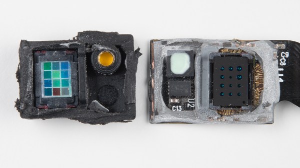
This tracker has a nice round e-paper screen, which could be a welcome part in a project if they start washing up on the shores of eBay. The rest of the watch is a basic Bluetooth low energy module and the accessory electronics wrapped in a squishy plastic casing.

There’s a lot of nice engineering inside the watch. As far as the electronics go, it’s very low power. On top of that is plenty of clever cost optimization; from a swath of test points to reduce quality issues in the hands of consumers to the clever stamped and formed battery tabs which touch the CR2032 that powers it.

The teardown covers more details: the switch, what may be hiding behind the epoxy globs, the plastics, and more. One thing that may be of interest to those that have been following Jenny’s excellent series is the BOM cost of the device. All in all a very educational read.

Russian Decapping Madness

It all started off innocently enough. [mretro] was curious about what was inside a sealed metal box, took a hacksaw to it and posted photographs up on the Interwebs. Over one hundred forum pages and several years later, the thread called (at least in Google Translate) “dissecting room” continues to amaze.

h_1466184174_4168461_2f4afb42b7If you like die shots, decaps, or teardowns of oddball Russian parts, this is like drinking from a firehose. You can of course translate the website, but it’s more fun to open it up in Russian and have a guess at what everything is before peeking. (Hint: don’t look at the part numbers. NE555 is apparently “NE555” in Russian.)

From a brief survey, a lot of these seem to be radio parts, and a lot of it is retro or obsolete. Forum user [lalka] seems to have opened up one of every possible Russian oscillator circuit. The website loads unfortunately slowly, at least where we are, but bear in mind that it’s got a lot of images. And if your fingers tire of clicking, note that the URL ends with the forum page number. It’d be a snap to web-scrape the whole darn thing overnight.

We love teardowns and chip shots, of old gear and of new. So when you think you’ve got a fake part, or if you need to gain access to stuff under that epoxy blob for whatever reason, no matter how embarrassing, bring along a camera and let us know!

Thanks [cfavreau] for the great tip!

Refurbishing Armored Tablets

Who can resist the insane deals on bizarre hardware that pop up on auction websites? Not [Dane Kouttron], for sure. He stumbled on Armor X7 ruggedized tablets, and had to buy a few. They’d be just perfect for datalogging in remote and/or hostile locations, if only they had better batteries and were outfitted with a GSM data modem… So [Dane] hauled out his screwdrivers and took stuff apart. What follows is a very detailed writeup of the battery management system (BMS), and a complete teardown of this interesting tablet almost as an afterthought.

First, [Dane] tried to just put a bunch more batteries into the thing, but the battery-management chip wouldn’t recognize them. For some inexplicable reason, [Dane] had the programmer for the BMS on-hand, as well as a Windows XP machine to run the antiquated software on. With the BMS firmware updated (and the manufacturer’s name changed to Dan-ger 300!) everything was good again.

Now you may not happen to have a bunch of surplus X7 ruggedized tablets lying around. Neither do we. But we can totally imagine needing to overhaul a battery system, and so it’s nice to have a peek behind the scenes in the BMS. File that away in your memory banks for when you need it. And if you need even more power, check out this writeup of reverse-engineering a Leaf battery pack. Power to the people!

Die Photos Of A Runner’s RFID Chip

A mass participation sporting event such as a road race presents a significant problem for its record keepers. It would be impossible to have ten thousand timekeepers hovering over stopwatches at the finish line, so how do they record each runner’s time? The answer lies in an RFID chip attached to the inside of the bib each runner wears, which is read as the runner crosses the line to ensure that their time is recorded among the hundreds of other participants.

[Ken Shirriff] got his hands on a bib from San Francisco’s “Bay to Breakers” race, and set about a teardown to lay bare its secrets.

The foil antenna pattern.

Stripping away the foam covering of the RFID assembly revealed a foil antenna for the 860-960MHz UHF band with the tiny RFID chip at its centre. The antenna is interesting, it’s a rather simple wideband dipole folded over with what looks like a matching stub arrangement and an arrow device incorporated into the fold that is probably for aesthetic rather than practical purposes. He identified the chip as an Impinj Monza 4, whose data sheet contains reference designs for antennas we’d expect to deliver a better performance.

After some trial-by-fire epoxy removal the tiny chip was revealed and photographed. It’s a device of three parts, the power scavenging and analog radio section, the non-volatile memory that carries the payload, and a finite-state logic machine to do the work. This isn’t a proper processor, instead it contains only the logic required to do the one task of returning the payload.

He finishes off with a comparison photograph of the chip — which is about the size of a grain of salt — atop a 1980s 8051-series microcontroller to show both its tiny size and the density advancements achieved over those intervening decades.

Since RFID devices are becoming a ubiquitous part of everyday life it is interesting to learn more about them through teardowns like this one. The chip here is a bit different to those you’ll find in more mundane applications in that it uses a much higher frequency, we’d be interested to know the RF field strength required at the finish line to activate it. It would also be interesting to know how the system handles collisions, with many runners passing the reader at once there must be a lot of RFID chatter on the airwaves.

We’ve featured [Ken]’s work before, among many others in his reverse engineering of Clive Sinclair’s 1974 scientific calculator, and his explanation of the inner workings of the TL431 voltage reference. Though we’ve had many RFID projects on these pages, this appears to be the first teardown of one we’ve covered.