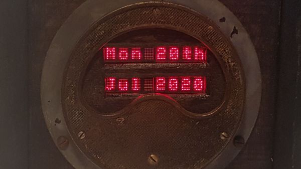
One time-proven method to make a lesson memorable is to make it a story, but that is not easy if your core material is the repair log of a rotted out analog ammeter. Most folks don’t need a 300A meter on their drill press, so [Build Comics] converted it to a text display and describes the procedure like they are writing a comic book. He is using HDLO-3416 LED cluster arrays for that dated-but-legible industrial feel, and everything looks right at home in a box made from oak and steel. Even the USB cord even gets a facelift by running it inside a fabric shoelace. In our own lives, covering charging cables is a hack on its own because we don’t want to fumble with the wrong charger when it is time to sleep or drive. Glow-in-the-dark cord upgrades, anyone?
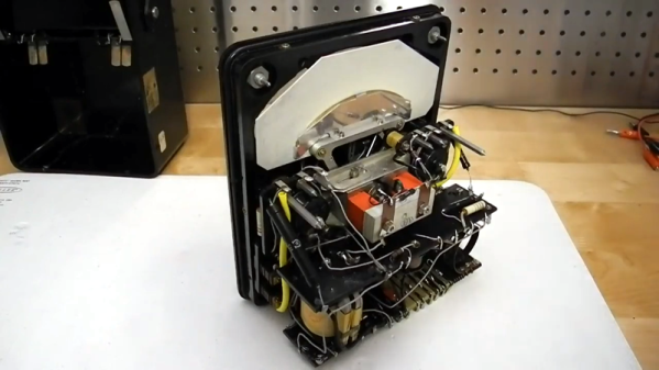
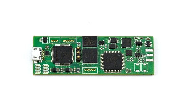
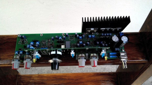
We don’t have a pre-operation picture of the subject, but the innards suggest that it comes from the bottom of an industrial scrap pile. There is a cross-hatch pattern on the front plate, which hinted at 3D printing, but if you look closely at the early images, you can see that it is original. There is a nodeMCU board to fetch the date information and control the four alphanumeric displays. Except for the red lights, all the new hardware hides behind wood or steel, so this old workhorse’s aesthetic lives on and has a story to share that is a delight to read.
If you enjoy reading [Build Comics] and their adventurous recollections, we forecast you’ll enjoy this weather display, or maybe it is time to check out their clock, but we want to plant the seed of literary build logs.