If you want to plug a USB cable into your next project, you’ve got a problem. USB is not UART, and UART is what every microcontroller serial port wants. To add USB to your microcontroller project, you’ll need to add a support chip, probably from FTDI, although there are a multitude of almost-FTDI clones available from the other parts of the Internet. These parts are slightly expensive, and they require some support circuitry. What you really need is a simple device that requires minimal external components, takes in serial from your microcontroller and spits out USB, and costs no more than a dollar. Bonus points if it’s hand-solderable.
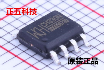 The CH330 is apparently the answer to this problem (That’s a TaoBao link, this is probably going to be the best link going forward). It’s a dead simple chip with eight pins. Two are the data lines on a USB cable, and two are TX and RX for your microcontroller. The other pins are just power, ground, and an RTS line. Best of all, it only costs about fifty cents. You’ve never heard about it, because a few hours after this post is published, it will be the most information you’re going to get on this chip in the English-speaking world.
As far as we can tell, the CH330 is the smallest in a line of USB to UART converters from WCH, although the part isn’t even on the company’s website. The first reference to the phrase ‘CH330’ in reference to a USB chip appeared about a month ago, at the beginning of September. There’s a GitHub for someone who is apparently using this chip in a Pine64 board, but that’s about it. There’s no more information.
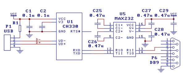
Right now, the only documentation for this chip is a single Chinese-language datasheet with an example schematic showing this chip connected to a MAX232 as a USB to RS232 converter. This is it. You’re looking at all the information that exists on this chip in the English-speaking version of the Internet.
The idea of a cheap, small chip that easily turns USB into UART would be great for thousands of projects. An FTDI chip will work, yes, but if you’re making thousands of a thing you might want to go with the fifty cent part over the two dollar part. That said, we’re in untested waters with this part, and you can’t even find it on AliExpress.
Let us know if you’ve gotten your hands on one of these devices. This has the potential to be really useful in a lot of projects and products, and we’re eager to see what the community comes up with. Thanks to [acabx] for sending this one in on the tip line.