“Nixie” Tubes Sound Good

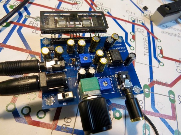
A tube is a tube is a tube. If one side emits electrons, another collects them, and a further terminal can block them, you just know that someone’s going to use it as an amplifier. And so when [Asa] had a bunch of odd Russian Numitron tubes on hand, an amplifier was pretty much a foregone conclusion.

A Numitron is a “low-voltage Nixie”, or more correctly a single-digit VFD in a Nixiesque form factor. So you could quibble that there’s nothing new here. But if you dig into the PDF writeup, you’ll find that the tubes have been very nicely characterised, situating this project halfway between dirty hack and quality lab work.

It’s been a while since we’ve run a VFD-based amplifier project, but it’s by no means the first time. Indeed, we seem to run one every couple years. For instance, here is a writeup from 2010, and the next in 2013. Extrapolating forward, you’re going to have to wait until 2019 before you see this topic again.

VFD Clock Only Speaks Romanian

There’s no shortage of clock projects, but [niq_ro] has his own take using a vacuum fluorescent display (VFD), and Arduino, and a pair of MAX6921 ICs. Those chips are made to drive a VFD, and the use of two of the ICs required a bit of work. The Arduino is not a great time keeper, so the clock also uses a DS3231 clock module and a humidity and temperature sensor.

The clock is in Romanian, although there are some options for different text. You can find the code on GitHub and can see the result in the video below.

Continue reading “VFD Clock Only Speaks Romanian”

[Sprite_tm] Gives Near Death VFD A Better Second Life

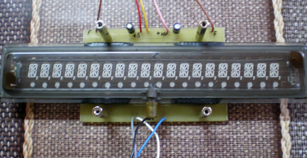
[Sprite_tm] picked up some used VFD displays for cheap, and wanted to make his own custom temperature and air-quality display. He did that, of course, but turned it into a colossal experiment in re-design to boot. What started out as a $6 used VFD becomes priceless with the addition of hours of high-powered hacking mojo.

You see, the phosphor screen had burnt-in spots where the old display was left static for too long. A normal person would either live with it or buy new displays. [Sprite_tm] ripped off the old display driver and drives the row and column shift registers using the DMA module on a Raspberry Pi2, coding up his own fast PWM/BCM hybrid scheme that can do greyscale.

He mapped out the individual pixels using a camera and post processing in The Gimp to establish the degradation of burnt-in pixels. He then re-wrote a previous custom driver project to compensate for the pixels’ inherent brightness in firmware. After all that work, he wrapped the whole thing up in a nice wooden frame.

There’s a lot to read, so just go hit up his website. High points include the shift-register-based driver transplant, the bit-angle modulation that was needed to get the necessary bit-depth for the grayscale, and the PHP script that does the photograph-based brightness correction.

Picking a favorite [Sprite_tm] hack is like picking a favorite ice-cream flavor: they’re all good. But his investigation into hard-drive controller chips still makes our head spin just a little bit. If you missed his talks about the Tamagotchi Singularity from the Hackaday SuperCon make sure you drop what you’re doing and watch it now.

VFD 430 Clock, NYC Style

[Daniel] seems to have a lot of time on his hands for building clocks, and that’s fine by us. For his latest build, he used a vacuum fluorescent display (VFD) to display hours, minutes, and seconds using an MSP430 to drive it.

Like the analog meter clock he built recently, there is no RTC. Instead, [Daniel] used the 430’s watchdog timer to generate 1Hz interrupts from the 430’s 32KHz clock. [Daniel] wanted to try Manhattan-style board construction for this project, so he built each module on a punch-cut stripboard island and super glued them to a copper-clad board. We have to agree with [Daniel] that the bare-bones construction is a nice complement to the aesthetic of the VFD.

[Daniel] set out to avoid using a VFD display driver, but each of the segments require +50V. He ran through a couple of drawing board ideas, such as using 17 transistors to drive them all before eventually settling on the MAX6921 VFD driver. The +50V comes from an open-loop boost converter he built that steps up from 12V.

The time is set with two interrupt-triggering buttons that use the shift register example from TI as a jumping off point. All of the code is available on [Daniel]’s site. Stick around after the break for a quick demo of the clock.

Continue reading “VFD 430 Clock, NYC Style”

Hacklet 44 – Teardowns

Just about every hacker, maker and tinkerer out there received their early education the same way: A screwdriver in one and a discarded bit of electronics in the other. There is no better way to find out how something works than cracking it open and examining each piece.  In recent years, teardown videos have become popular on YouTube, with some of the great examples coming from users like [EEVblog], [mikeselectricstuff], and [The Geek Group]. This week’s Hacklet is all about the best teardown projects on Hackaday.io!

copierWe start with [zakqwy] and his Savin C2020 Teardown. Photocopiers (and multifunction machines) are the workhorses of the modern office. This means there are plenty of used, abused, and outdated photocopiers available to hackers. [Zakqwy] got this monster when it started misbehaving at his office. Copiers are a venerable cornucopia of motors, gears, sensors (lots and lots of breakbeam sensors) and optics. The downside is toner: it’s messy, really bad to breathe, and if you don’t wear gloves it gets down into the pores of your skin, which takes forever to get out. [Zakqwy] persevered and found some awesome parts in his copier – like an  Archimedes’ screw used to transport black toner.

wemoNext up is [Bob Blake] with Belkin WeMo Insight Teardown. [Bob] wanted a WiFi outlet, but wasn’t about to plug something in to both his power grid and his network without taking it apart first. [Bob] did an awesome job of documenting his teardown with lots of great high resolution photos – we love this stuff! He found a rather well thought out hardware design. The Insight has 3 interconnected PCBs inside. The power switching and supply circuits are all on one board. It includes slots and the proper creep distances one would expect in a design that will be carrying 120V AC mains power. A small daughter board holds an unknown chip – [Bob] is guessing it is the power sensing circuitry. A third board a tucked in at the top of the module holds the main CPU, a Ralink/MediaTek RT5350F SoC, RAM, and the all important WiFi antenna.


x-ray[Drhatch] took things into the danger zone with an X-ray Head Teardown. We’re not sure if [Drhatch] is a real doctor, but he does have a Heliodent MD dental X-ray head. Modern X-ray machines are generally radiation safe if they’re not powered up. Radiation isn’t the only dangers to worry about though – there are latent charged capacitors and cooling oils which may contain nasty chemicals like PCBs, among other things. [Drhatch] found some pretty interesting design decisions in his X-ray head. The tube actually fires through the cylindrical high voltage transformer. This means the transformer acts as a beam collimator, focusing the X-ray beam down like a lens. He also found plenty of lead shielding. Interestingly there are two thickness of lead in the housing. Shielding close to the tube is 1 mm thick, while shielding a bit further away is only 0.7 mm thick.


3phaseFinally, we have [danielmiester] with Inside a 3ph AC Motor Controller(VFD). [Daniel] tore down a Hitachi Variable-Frequency Drive (VFD) with the hopes of creating a frequency converter for a project. These high voltage, high power devices have quite a bit going on inside, so the conversion became a teardown project all its own. VFDs such as this one are used in industry to drive high power AC motors at varying speeds efficiently. As [Daniel] says, the cheaper ones are ” just really fancy PWM modules”. Handling 1.5 kW is no joke though. This VFD had a large brick of power transistors potted into its heat sink. The controller board was directly soldered to the transistors, as well as the rectifier diodes for the DC power supply. [Daniel] was doing some testing with the unit powered up, so he built a custom capacitor discharge unit from 3 C7 Christmas lights. Not only did they keep the capacitors discharged, they provided an indication that the unit was safe. No light means no charge.

Not satisfied? Want more teardown goodness? Check out our freshly minted Teardown List!

That’s about all the time we have for this week’s Hacklet. As always, see you next week. Same hack time, same hack channel, bringing you the best of Hackaday.io!

Reverse Engineer A VFD After Exploring How They Work

[Dave Jones] got his hands on a really wide, 2-row Vacuum Fluorescent Display. We’ve come across these units in old equipment before and you can get them from the usual sources, both new and used, but you need to know how to drive them. This recent installment of the EEVblog reverse engineers this VFD.

The function of these displays is pretty easy to understand, and [Dave] covers that early in the video after the break. There is a cathode wire and phosphorescent coated anodes. When current is applied the anodes glow. To add control of which anodes are glowing a mesh grid is placed between the anodes and the cathode wire. Applying negative potential to the grid prevents the electrons from traveling to the anode so that area will not be lit.

Now driving this low-level stuff is not easy, but rest assured that most VFDs you find are going to have a driver attached to them. The reverse engineering is to figure out the protocol used to control that driver. On this board there is a 2-pin connector with a big electrolytic filtering cap which is a dead giveaway for power rails. Looking at the on-board processor which connects directly he ascertains that the input will be 5V regulated since this is what that chip will expect. Connecting his bench supply yields a blinking cursor! [Dave] goes on to pump parallel data and test out the control pins all using an Arduino. He finds success, sharing many great reverse engineering tips along the way.

We often call this type of thing a dark art, but that’s really just because there aren’t a lot of people who feel totally comfortable giving it a try. We think that needs to change, so follow this example and also go look at [Ben Heckendorn’s] recent LCD reverse engineering, then grab some equipment and give it a try for yourself. We want to hear about your accomplishments!

Continue reading “Reverse Engineer A VFD After Exploring How They Work”

VFD Wristwatch

The ChronodeVFD Wristwatch

Not just another steampunk fashion statement, [Johngineer’s] ChronodeVFD wristwatch is as intricate as it is beautiful. Sure, we’ve seen our share of VFD builds (and if you want a crash course in vacuum fluorescent displays, check out Fran’s video from earlier this year) but we seldom see them as portable timepieces, much less ones this striking.

The ChronodeVFD uses a IVL2-7/5 display tube, which in addition to being small and low-current is also flat rather than rounded, and features a transparent backing. [Johngineer] made a custom board based around an AtMega88 and a Maxim DS3231 RTC (real time clock): the latter he admits is a bit expensive, but no one complains about left-overs that simplify your design.

The VFD runs off a Maxim MAX6920 12-bit shift register and is powered by a single alkaline AA battery. A rechargable NiMH would have been preferable, but the lower nominal voltage meant lower efficiency for his boost converters and less current for the VFD. [Johngineer] won’t get much more than 6-10 hours of life, but ultimately the ChronodeVFD is a costume piece not meant for daily wear. Swing by his blog for a number of high-res photos and further details on how he built the brass tubing “roll cage” enclosure as well as the mounts for the leather strap.