If you want to talk about antennas, the amateur radio community has you covered, with one glaring exception. Very low frequency and Extremely Low Frequency radio isn’t practiced very much, ultimately because it’s impractical and you simply can’t transmit much information when your carrier frequency is measured in tens of Hertz. There is more information on Extremely Low Frequency radio in Michael Crichton’s Sphere than there is in the normal parts of the Internet. Now there might be an easier way to play with VLF radiation, thanks to developers at the National Accelerator Laboratory. They’ve developed a piezoelectric transmitter for very long wavelengths.
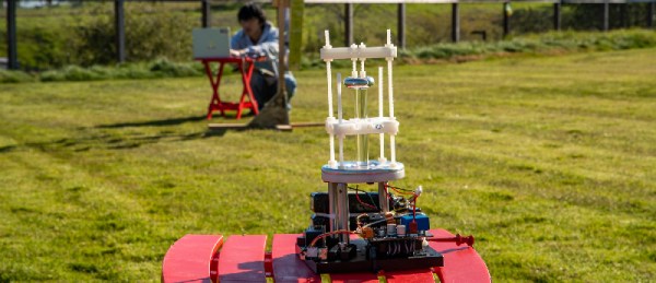
Instead of pushing pixies through an antenna, this antenna uses a rod-shaped crystal of lithium niobate, a piezoelectric material. An AC voltage is applied to the rod makes it vibrate, and this triggers an oscillating electric current flow that’s emitted as VLF radiation. The key is that it’s these soundwaves bouncing around that define the resonant frequency, and the speed of sound in lithium niobate is a lot slower than the speed of light, but they’re translated into electric signals because of its piezoelectricity. For contrast, if this were a wire quarter-wave antenna it would be tens of kilometers long.
The application for this sort of antenna is ideally for where regular radio doesn’t work. Radio doesn’t work underwater, but nuclear subs trail an antenna out of the back to receive messages using Extremely Low Frequency radio. A walkie talkie doesn’t work in a mine, and this could potentially be used there. There is a patent for this piezoelectric antenna, so if anyone knows of a source of lithium niobate, put a link in the comments.
We’ve seen this trick before to make small antennas even smaller, but this is the first time we’ve seen it used in the VLF band, where it’s arguably even more impressive.


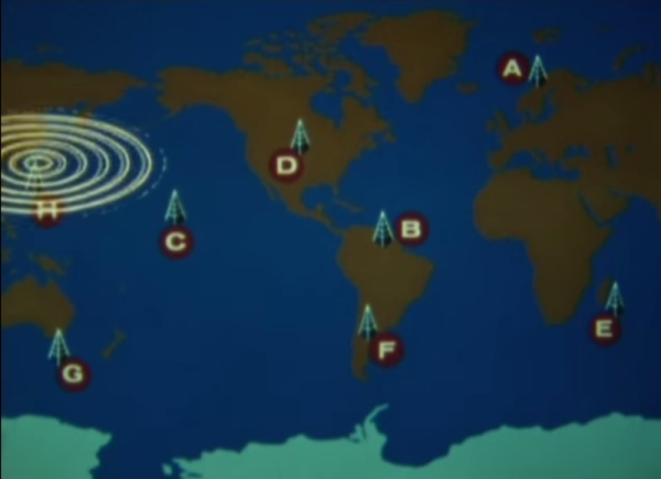
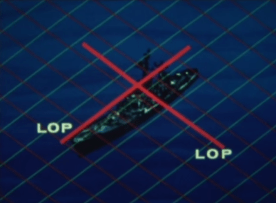 A ship’s receiving equipment performed navigation by comparing the phase difference between detected signals. This calculation was based around “lanes” that served to divvy up the distance between stations into equal divisions. A grid of these lanes formed by eight stations’ worth of overlapping signals provides intersecting lines of position (LOP) that give the sailor his fix.