
The itch to investigate lurks within all us hackers. Sometimes, you just have to pull something apart to learn how it works. [Stephen Crosby] found himself doing just that when he got his hands on a Flume water monitor.
[Stephen] came by the monitor thanks to a city rebate, which lowered the cost of the Flume device. It consists of two main components: a sensor which is strapped to the water meter, and a separate “bridge” device that receives information from the sensor and delivers it to Flume servers via WiFi. There’s a useful API for customers, and it’s even able to integrate with a Home Assistant plugin. [Stephen] hoped to learn more about the device so he could scrape raw data himself, without having to rely on Flume’s servers.
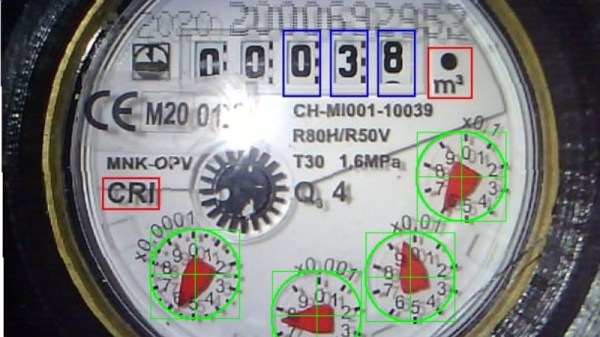
Through his reverse engineering efforts, [Stephen] was able to glean how the system worked. He guides us through the basic components of the battery-powered magnetometer sensor, which senses the motion of metering components in the water meter. He also explains how it communicates with a packet radio module to the main “bridge” device, and elucidates how he came to decompile the bridge’s software.
When he sent this one in, [Stephen] mentioned the considerable effort that went into reverse engineering the system was “a very poor use” of his time — but we’d beg to differ. In our book, taking on a new project is always worthwhile if you learned something along the way. Meanwhile, if you’ve been pulling apart some weird esoteric commercial device, don’t hesitate to let us know what you found!
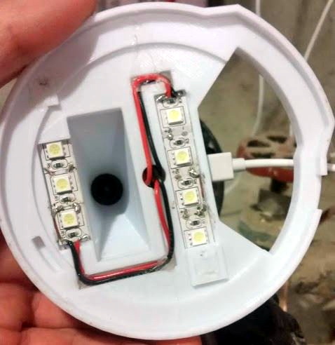
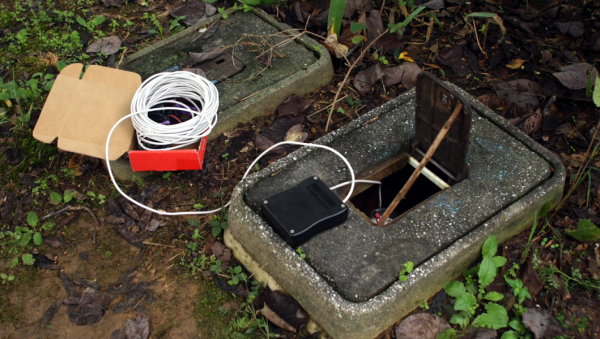
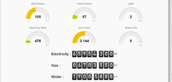
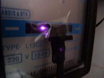 So he figured out a way to extract data from the existing meters. For the Electricity meter, he thought of using current clamps, but punted that idea considering them to be suited more for instantaneous readings and prone for significant drift when measuring cumulative consumption. Eventually, he hit upon a pretty neat hack. He took a slot type opto coupler, cut it in half, and used it as a retro-reflective sensor that detected the black band on the spinning disk of the old electro-mechanical meter. Each turn of the disk corresponds to 4 Watt-hours. A little computation, and he’s able to deduce Watt-hours and Amps used. The sensor is hooked up to an Arduino Pro-mini which then sends the data via a nRF24L01+ module to the main circuit located inside his house. The electronics are housed in a small enclosure, and the opto-sensor looks just taped to the meter. He has a nice tip on aligning the infra-red opto-sensor – use a camera to check it (a phone camera can work well).


