Rapidly Prototyping RF Filters

RF filters are really just a handful of strategically placed inductors and capacitors. Yes, you can make a 1 GHz filter out of through-hole components, but the leads on the parts turn into inductors at those frequencies, completely ruining the expected results in a design.

The solution to this is microstrip antennas, or carefully arranged tracks and pads on a PCB. Anyone can build one of these with Eagle or KiCad, but that means waiting for an order from a board house to verify your design. [VK2SEB] has a better idea for prototyping PCB filters: use copper tape on blank FR4 sheets.

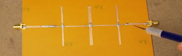
The first, and simplest, filter demonstrated is a simple bandstop filter. This is really just a piece of fiberglass with copper laminated to one side. Two RF connectors are soldered to the edges and a strip of copper tape strung between them. Somewhere around the middle of this copper tape, [VK2SEB] put another strip of copper tape in a ‘T’ configuration. This is the simplest bandstop filter you can make, and the beauty of this construction is that it can be tuned with a razor blade.

Of course, a filter can only be built with copper tape if you can design them, and for that [SEB] is turning to software. The Qucs project is a software tool for designing and simulating these microstrip filters, and after inputting the correct parameters, [SEB] got a nice diagram of what the filter should look like. A bit of taping, razor blading, and soldering and [SEB] had a working filter connected to a spectrum analyzer. Did it work? To a limited extent; the PCB material probably wasn’t right, and board houses are more accurate than a razor blade, but [SEB] did manage to create a 10 GHz filter out of fiberglass and copper tape.

You can check out the video for this experiment below.

Continue reading “Rapidly Prototyping RF Filters”

Fail Of The Week: How Not To Use Pushbuttons

If you are a regular at creating printed circuit boards, it is likely that somewhere in your shop there will be a discard pile of boards on which you placed a component in the wrong orientation such that it would not work. It’s easily done, and don’t be shy to admit it if it’s happened to you.

[Bill] was making his own ARM developer board, taking inspiration from the ARM Pro Mini. He produced his PCB design and sent it off to the board house, and in due course received and reflow soldered a batch of beautiful dev boards. On power-up though, something was wrong! No USB device detected on his computer, a disaster. A lot of studying board and schematic led to the discovery that his push-button switches had been placed at 90 degrees to the orientation it should have had, leaving them in a permanently “on” position.

The PCB bug makes this is a Fail Of The Week post, but he transformed into a win with some experimentation with the switch outline in KiCAD before finding a way to mount the switches on the pads at 45 degrees, covering three of the pads. Well done, and well done for admitting the error.

[Editor’s note: been there, done that. One way to prevent the error is to only connect to diagonally opposite pins of the tact switch, so the rotation doesn’t matter.]

Having earlier asked others to come clean with their PCB mistakes, it’s probably appropriate to admit that Hackaday scribes are just as fallible as [Bill] when it comes to PCB layouts. Somewhere there may still be a board on this bench with a QFN microcontroller bodged on at 90 degrees to its original orientation, with cut tracks and tiny wire runs.

Whether you are a seasoned PCB pro or a wet-behind-the-ears rookie, our Creating a PCB In Everything series should be of interest.

Make A Bit Of Cloth With This 3D Printable Loom

When the hackspace where this is being written created their textile room, a member who had previously been known only for her other work unexpectedly revealed herself to be a weaver, and offered the loan of a table-top loom. When set up, it provided an introduction to the art of weaving for the members of all different interests and backgrounds, and many of them have been found laying down a few lines of weft. It’s a simple yet compelling piece of making which  captivates even people who might never have considered themselves interested in textiles.

If you are not lucky enough to have a friendly hackspace member with a spare loom when you wish to try your hand at weaving, you may be interested in this Thingiverse project, a 3D printable rigid heddle loom. It’s not the most complex of looms, the heddle is the part that lifts the warp threads up and down, and it being the rigid variety means that this loom can’t do some of the really fancy tricks you’ll see on other types of loom. But it’s a functional loom that will allow you to try your hand at weaving for the expenditure of not a lot of money, some 3D printer filament, and some PVC pipe. If your hackspace or bench has an area devoted to textiles, it may find a place.

We’ve shown you a few looms on these pages over the years, but mostly of the more mechanised variety. A Raspberry Pi automated loom for example, or a CNC Jacquard loom.

Thanks to our Shenzhen contributor-at-large, [Naomi Wu] for the tip.

Smart Gun Beaten By Dumb Magnets

[Plore], a hacker with an interest in safe cracking, read a vehemently anti-smart-gun thread in 2015. With the words “Could you imagine what the guys at DEF CON could do with this?” [Plore] knew what he had to do: hack some smart guns. Watch the video below the break.

Armed with the Armatix IP1, [Plore] started with one of the oldest tricks in the book: an RF relay attack. The Armatix IP1 is designed to fire only when a corresponding watch is nearby, indicating that a trusted individual is the one holding the gun. However, by using a custom-built $20 amplifier to extend the range of the watch, [Plore] is able to fire the gun more than ten feet away, which is more than enough distance to be dangerous and certainly more than the few inches the manufacturers intended.

Not stopping there, [Plore] went to the other extreme, creating what he calls an “electromagnetic compatibility tester” (in other words, a jammer) that jams the signal from the watch, effectively preventing a legitimate gun owner from firing their gun at 10 to 20 feet!

Not one to call it quits, [Plore] realised that the gun prevented illicit firing with a simple metal pin which it moved out of the way once it sensed the watch nearby. However, this metal just happened to be ferrous, and you know what that means: [Plore], with the help of some strong magnets, was able to move the pin without any electrical trickery.

Now, we’ve already covered the many hurdles that smart guns face, and this specific investigation of the state of smart gun technology doesn’t make the picture look any brighter. We’re aware that hindsight is always 20/20, so let us know in the comments how you would fix the problems with the Armatix IP1.
Continue reading “Smart Gun Beaten By Dumb Magnets”

Hackaday Prize Entry: USB Packet Snooping

Sometimes you run into a few problems when developing your own hardware, and to solve these problems you have to build your own tools. This is exactly how [KC Lee]’s USB Packet Snooper was created. It’s a small device that allows for capturing and analyzing Full Speed USB traffic to debug one of [KC]’s other Hackaday Prize entries.

[KC] is building an HID Multimedia Dial for this year’s Hackaday Prize. It’s kind of like the Microsoft Surface Dial or the ubiquitous Griffin PowerMate that has been on the market for the better part of two decades. This multimedia dial is bitbanging USB with an STM8, which means [KC] needs a tool to capture raw USB packets.

The design of this USB Packet Snooper is split up into two parts. The first is either a dongle or a pass-through device that simply serves as a tap between a USB device and a USB host. The logging and analysis board attaches to this dongle, and uses a rather fast ARM microcontroller to listen in on USB packets and send everything over serial to a PC.

This is a rather novel device; V-USB is limited to Low Speed USB, and other USB capture tools are far out of reach of the hobbyist budget. Software solutions on a PC obviously won’t work because [KC] doesn’t even know if he’s sending valid USB packets. This is a great tool that finally brings hobbyist-level USB analysis up to Full Speed USB.

KIM-1 To COSMAC Elf Conversion — Sort Of

In the mid-1970s, if you had your own computer, you probably built it. If you had a lot of money and considerable building skill, you could make an Altair 8800 for about $395 — better than the $650 to have it built. However, cheaper alternatives were not far behind.

In 1976, Popular Electronics published plans for a computer called the COSMAC Elf which you could build for under $100, and much less if you had a good junk box. The design was simple enough that you could build it on a piece of perf board or using wire wrap. We featured the online archive of the entire Popular Electronics collection, but hit up page 33 of this PDF if you want to jump right to the article that started it all. The COSMAC Elf is a great little machine built around a 40-pin RCA 1802 processor, and for many was the first computer they owned. I lost my original 1802 computer in a storm and my recent rebuild in another completely different kind of storm. But there is a way to reclaim those glory days without starting from scratch.  I’m going to repurpose another retro-computing recreation; the KIM-1.

I’ll admit it, Rewiring a real KIM-1 to take an 1802 CPU would be difficult and unnecessary and that’s not what this article is about. However, I did have a KIM UNO — [Oscar’s] respin of the classic computer using an Arduino mini pro. Looking at the keyboard, it occurred to me that the Arduino could just as easily simulate an 1802 as it could a 6502. Heck, that’s only two digits different, right?

The result is pretty pleasing. A “real” Elf had 8 toggle switches, but there were several variations that did have keypads, so it isn’t that far off. Most Elf computers had 256 bytes of memory (without an upgrade) but the 1802 UNO (as I’m calling it) has 1K. There’s also a host of other features, including a ROM and a monitor for loading and debugging programs that doesn’t require any space in the emulated 1802.

Continue reading “KIM-1 To COSMAC Elf Conversion — Sort Of”

Sunday: Breakfast At DEF CON

Nurse your hangover by having Breakfast at DEF CON with Hackaday this Sunday. You’re invited to our yearly ritual by marking the beginning of the end with coffee and pastries at 10:30 am.

Choosing an exact location in advance is always tricky (anyone who’s been to DEF CON understands). We’ll pick a place once we hit town later this week. For now, head over to the Breakfast at DEF CON event page and hit the “join the team” button on the bottom left so we can let you know when we’ve found the perfect location for the breakfast meetup.

Extra internet points go to those who bring some hardware to show off… and especially for anyone who is making this the end of their Saturday rather than the beginning of Sunday. [Brian] and [Mike] will be there, joined by our friends [Jasmine] and [Shulie] who are on the scene for Tindie, a sponsor of the IoT Village this year. See you on Sunday!