Writing An OLED Display Driver In MicroZig

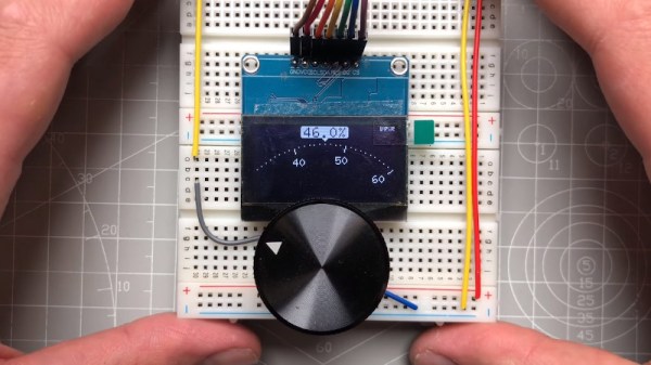
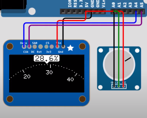
Although most people would use C, C++ or MicroPython for programming microcontrollers, there are a few more obscure options out there as well, with MicroZig being one of them. Recently [Andrew Conlin] wrote about how to use MicroZig with the Raspberry Pi RP2040 MCU, showing the process of writing an SSD1306 OLED display driver and running it. Although MicroZig has since published a built-in version, the blog post gives a good impression of what developing with MicroZig is like.

Zig is a programming language which seeks to improve on the C language, adding memory safety, safe pointers (via option types), while keeping as much as possible of what makes C so useful for low-level development intact. The MicroZig project customizes Zig for use in embedded projects,  targeting platforms including the Raspberry Pi MCUs and STM32.  During [Andrew]’s usage of MicroZig it was less the language or supplied tooling that tripped him up, and more just the convoluted initialization of the SSD1306 controller, which is probably a good sign. The resulting project code can be found on his GitHub page.

RGB LED Display Simply Solves The Ping-Pong Ball Problem

A few years ago [Brian McCafferty] created a nice big RGB LED panel in a poster frame that aimed to be easy to move, program, and display. We’d like to draw particular attention to one of his construction methods. On the software end of things there are multiple ways to get images onto a DIY RGB panel, but his assembly technique is worth keeping in mind.

The diameter of ping pong balls is a mismatch for the spacing of LEDs on a strip. The solution? A bit of force.

The technique we want to highlight is not the fact that he used table tennis balls as the diffusers, but rather the particular manner in which he used them. As diffusers, ping-pong balls are economical and they’re effective. But you know what else they are? An inconvenient size!

An LED strip with 30 LEDs per meter puts individual LEDs about 33 mm apart. A regulation ping-pong ball is 40 mm in diameter, making them just a wee bit too big to fit nicely. We’ve seen projects avoid this problem with modular frames that optimize spacing and layout. But [Brian]’s solution was simply to use force.

Observing that ping-pong balls don’t put up much of a fight and the size mismatch was relatively small, he just shoved those (slightly squashy) 40 mm globes into 33 mm spacing. It actually looks… perfectly fine!

We suspect that this method doesn’t scale indefinitely. Probably large displays like this 1200 pixel wall are not the right place to force a square peg into a round hole, but it sure seemed to hit the spot for his poster-sized display. Watch it in action in the video below, or see additional details on the project’s GitHub repository.

Continue reading “RGB LED Display Simply Solves The Ping-Pong Ball Problem”

Using An OLED Display’s Light For Embedded Sensors

These days displays are increasingly expected to be bidirectional devices, accepting not only touch inputs, but also to integrate fingerprint sensing and even somehow combine a camera with a display without punching a hole through said display. Used primarily on smartphone displays, these attempts have been met with varying degrees of success. But a paper published in the Communications Engineering journal describes a version which combines an OLED with photosensors in the same structure — a design that may provide a way to make such features much more effective.

The article by [Chul Kim] and colleagues of the Samsung Display Research Center in South Korea the construction of these bidirectional OLED displays is described, featuring the standard OLED pixels as well as an organic photodiode (OPD) placed side-by-side. Focusing on the OLED’s green light for its absorption characteristics with the human skin, the researchers were able to use the produced OLED/OPD hybrid display for fingerprint recognition, as well as a range of cardiovascular markers, including heart rate, blood pressure, etc.

The basic principle behind these measurements involves photoplethysmography, which is commonly used in commercially available pulse oximeters. Before these hybrid displays can make their way into commercial devices, there are still a few technical challenges to deal with, in particular electrical and optical leakage. The sample demonstrated appears to work well in this regard, but the proof is always in the transition from the lab to mass-production. We have to admit that it would be rather cool to have a display that can also handle touch, fingerprints and record PPG data without any special layers or sensor chips.

OLED Display Lets Vintage PC Engage Turbo Mode In Style

Back in the 486 days, it was common to see a “Turbo” button on the front panel of many PCs, which was used to toggle between the CPU’s maximum speed and a slower clock rate that was sometimes necessary for compatibility with older software. Usually an LED would light up to show you were running at this higher speed, or if your machine was very fancy, it might even have a numerical display that would show the current CPU frequency.

[Joshua Woehlke] wanted to add a similar display to his 486, but figured that with modern technology, he could do something a bit more interesting. Especially when he realized that the spot on his case where the two-digit LED display would have originally been mounted was the perfect size to hold a common 0.96″ SSD1306 OLED. From there it was just a matter of wiring it up to an Arduino and writing some code to display different graphics depending on the computer’s current CPU speed.

Just like the frequency indicators of yore, the Arduino doesn’t actually measure the CPU’s frequency, it’s simply reading the state of the Turbo LED on the front panel. When the LED is off the Arduino shows an image of a i8088 CPU on the screen to indicate the computer is running in compatibility mode, and when the LED is on, the screen shows the Cyrix Cx486 DX2 logo. When the button hasn’t been pressed in awhile, the display defaults to a star field screensaver.

Regular readers may recall we recently covered a similar project that used an Arduino to add a little flair to an era appropriate seven-segment LED display. We’d say there’s still a good deal of romanticism about computers having a big “TURBO” button you can smash whenever you feel the need for speed.

LED Displays May Get Vertical Integration

If you zoom into the screen you are reading this on, you’d see an extremely fine pattern of red, green, and blue emitters, probably LEDs of some kind. This somewhat limits the resolution you can obtain since you have to cram three LEDs into each screen pixel. Engineers at MIT, however, want to do it differently. By growing thin LED films and sandwiching them together, they can produce 4-micron-wide LEDs that produce the full range of color, with each color part of a vertical stack of LEDs.

To put things in perspective, a standard TV LED is at least 200 microns across. Mini LEDs measure upwards of 100 microns, and micro LEDs are the smallest of all. A key factor for displays is the pitch — the distance from the center of one pixel to the center of the next. For example, the 44mm version of the Apple Watch has a pitch of around 77 microns. A Samsung Galaxy 10 is just over 46 microns.  This is important because it sets the minimum size for a high-resolution screen, especially if you are building large screens (such as when you build custom video walls (see the video below for more about that).

Continue reading “LED Displays May Get Vertical Integration”

tiny surface mount seven segment display

Nano-Sized 7-Segment LED Display On A Surface Mount Module

Inspired by a prank tweet, [Sam Ettinger] endeavored to create an SMD seven-segment display.  The NanoRaptor NanoSegment implements a panel of seven-segment display modules sized at “0806” each or just a bit wider than a standard 0805 SMD footprint.  Each of the seven segments is a single 0201 LED.  Six I/O lines and three resistors are required to operate each module.

To demonstrate the operation of his tiny display modules, Sam also created the “6Pin 7Seg” development board featuring an ATtiny84 microcontroller coupled to PCB footprints sized to receive the NanoRaptor NanoSegment display modules.  A demonstration of the board counts through digits displayed on one of the tiny seven-segment modules.

Hoping to reduce the module’s interface to two pins, Sam is now experimenting with a seven-segment display on a flex PCB that folds up into a 1208 footprint.  He is attempting to fold the resistors and a ATtiny20 microcontroller into an “origami PCB” configuration.

If these hacks are getting a little too small for your tastes, we’ve got you covered with this giant seven-segment display.


OLED Display Kicks Knob Up Several Accurate Notches

As far as input devices go, the potentiometer is pretty straightforward: turn it left, turn it right, and you’ve pretty much seen all there is to see. For many applications that’s all you need, but we can certainly improve on the experience with modern technology. Enter this promising project from [upir] that pairs a common potentiometer with a cheap OLED display to make for a considerably more engaging user experience.

To save time, the code is fine tuned in a simulator.

The basic idea is to mount the display over the potentiometer knob so you can show useful information such a label that shows what it does, and a readout of the currently detected value. But you’ll likely want to show where the knob is currently set within the range of possible values as well, and that’s where things get interesting.

In the video after the break, [upir] spends a considerable amount of time explaining the math behind details like the scrolling tick marks. The nearly 45 minute long video wraps up with some optimization, as getting the display to move along with the knob in real-time on an Arduino UNO took a bit of extra effort. The final result looks great, and promises to be a relatively cheap way to add an elegant and functional bit of flair to an otherwise basic knob.

With the code and this extensive demonstration of how it all works, adding a similar capability to your next knob-equipped gadget shouldn’t be too much of a challenge. Perhaps it could even be combined with the OLED VU meters we’ve covered previously. Be sure to let us know if you end up using this technique, as we’d love to see it in action.

Continue reading “OLED Display Kicks Knob Up Several Accurate Notches”