Downloading Satellite Imagery With A Wi-Fi Antenna

Over the past century or so we’ve come up with some clever ways of manipulating photons to do all kinds of interesting things. From lighting to televisions and computer screens to communication, including radio and fiber-optics, there’s a lot that can be done with these wave-particles and a lot of overlap in their uses as well. That’s why you can take something like a fairly standard Wi-Fi antenna meant for fairly short-range communication and use it for some other interesting tasks like downloading satellite data.

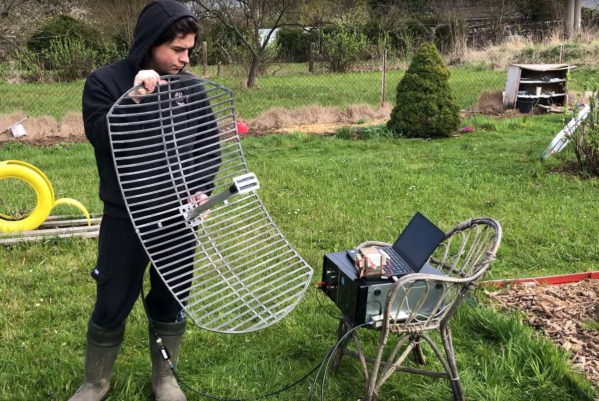
Weather satellites specifically use about the same frequency range as Wi-Fi, but need a bit of help to span the enormous distance. Normally Wi-Fi only has a range in the tens of meters, but attaching a parabolic dish to an antenna can increase the range by several orders of magnitude. The dish [dereksgc] found is meant for long-range Wi-Fi networking but got these parabolic reflectors specifically to track satellites and download the information they send back to earth. Weather satellites are generally the target here, and although the photons here are slightly less energy at 1.7 GHz, this is close enough to the 2.4 GHz antenna design for Wi-Fi to be perfectly workable and presumably will work even better in the S-band at around 2.2 GHz.

For this to work, [dereksgc] isn’t even using a dedicated tracking system to aim the dish at the satellites automatically; just holding it by hand is enough to get a readable signal from the satellite, especially if the satellite is in a geostationary orbit. You’ll likely have better results with something a little more precise and automated, but for a quick and easy solution a surprisingly small amount of gear is actually needed for satellite communication.
Continue reading “Downloading Satellite Imagery With A Wi-Fi Antenna”

Reverse Engineering The Quansheng Hardware

In the world of cheap amateur radio transceivers, the Quansheng UV-K5 can’t be beaten for hackability. But pretty much every hack we’ve seen so far focuses on the firmware. What about the hardware?

To answer that question, [mentalDetector] enlisted the help of a few compatriots and vivisected a UV-K5 to find out what makes it tick. The result is a complete hardware description of the radio, including schematics, PCB design files, and 3D renders. The radio was a malfunctioning unit that was donated by collaborator [Manuel], who desoldered all the components and measured which ones he could to determine specific values. The parts that resisted his investigations got bundled up along with the stripped PCB to [mentalDetector], who used a NanoVNA to characterize them as well as possible. Documentation was up to collaborator [Ludwich], who also made tweaks to the schematic as it developed.

PCB reverse engineering was pretty intense. The front and back of the PCB — rev 1.4, for those playing along at home — were carefully photographed before getting the sandpaper treatment to reveal the inner two layers. The result was a series of high-resolution photos that were aligned to show which traces connected to which components or vias, which led to the finished schematics. There are still a few unknown components, The schematic has a few components crossed out, mostly capacitors by the look of it, representing unpopulated pads on the PCB.

Hats off to the team for the work here, which should make hardware hacks on the radio much easier. We’re looking forward to what’ll come from this effort. If you want to check out some of the firmware exploits that have already been accomplished on this radio, check out the Trojan Pong upgrade, or the possibilities of band expansion. We’ve also seen a mixed hardware-firmware upgrade that really shines.

AM Radio Broadcast Uses Phasor To Let Eight Towers Spray One Big Signal

If you’re in the commercial AM radio business, you want to send your signal as far and wide as possible. More listeners means you can make more ad revenue, after all. [Jeff Geerling] recently visited a tower site for WSDZ-AM, which uses a full eight towers to broadcast its 20kW AM signal. To do that, it needs a phasor to keep everything in tune. Or, uh… phase.

The phasor uses a bunch of variable inductors and capacitors to manage the phase of the signal fed to each tower. Basically, by varying the phase of the AM signal going to each of the 8 transmitter towers, it’s possible to tune the directionality of the tower array. This allows the station to ensure it’s only broadcasting to the area it’s legally licensed to do so.

The tower array is also configured to broadcast slightly differently during the day and at night to account for the differences in propagation that occur. A certain subset of the 8 towers are used for the day propagation pattern, while a different subset is used to shape the pattern for the night shift. AM signals can go far farther at night, so it’s important for stations to vary their output to avoid swamping neighbouring stations when the sun goes down.

[Jeff’s] video is a great tour of a working AM broadcast transmitter. If you’ve ever wondered about the hardware running your local commercial station, this is the insight you’re looking for. AM radio may be old-school, but it continues to fascinate us to this day. Video after the break.

Continue reading “AM Radio Broadcast Uses Phasor To Let Eight Towers Spray One Big Signal”

Measuring An Unknown Velocity Factor

When is the speed of light not the speed of light? Of course, that’s a trick question. The speed of light may be constant, but just as sound travels at different speeds in different media, electronic signals move through transmission lines at a reduced speed. When you have a known cable, you can look up the velocity factor and use it to approximate the length of cable to have a given effective length. But what if you don’t know what kind of cable you have? [More Than Electronics] used a scope to measure it. You can see what he did in the video below.

For example, RG-8/U has a factor of 0.77. Even air isn’t exactly a factor of 1, although it is close enough that, in practice, we pretend that it is. If you wonder why it matters, consider stubs. Suppose you have a 300 MHz signal (handy because that’s 1 meter in wavelength; well, OK, pick 299.792 MHz if you prefer). If you have a quarter wavelength piece of coax shorted at one end, it will attenuate signals at 300 MHz. To understand why, picture the wave on the stub. If the close end of the stub is at 0 volts, then the other end — because it is a quarter wavelength away — must be at the maximum positive voltage or the minimum negative voltage. If either of the extremes is at the close end, then the far end must be at zero volts. That means the maximum current flows only when the signal is at 300 MHz.

Continue reading “Measuring An Unknown Velocity Factor”

Crystal Radio Kit From The 1970s

If you read the December 1970 issue of Mechanix Illustrated, you’d be treated to [Len Buckwalter]’s crystal radio build. He called out Modern Radio Labs as the supplier for parts. That company, run by [Elmer Osterhoudt], got so many inquiries that he produced a kit, the #74 crystal set. [Michael Simpson] found an unopened kit on eBay and — after a bidding war, took possession of the kit. The kit looked totally untouched. The crystal detector was still in the box, and there were period-appropriate newspaper wrappings.

The kit itself isn’t that remarkable, but it is a classic. An oatmeal box serves as a coil form. There’s a capacitor, a crystal detector, and headphones. The original cost of the parts was $7, but we imagine the eBay auction exceeded that by a large amount.

If the name [Len Buckwalter] sounds familiar, he was quite prolific in magazines like Electronics Illustrated and also wrote several books about transistors. [Michael] also shows off his innovative coil winder made from plastic cups and a coat hanger.

We’d love to find some old kits like this, although, from one way of thinking, it is almost a shame to build them after all these years. With an added audio amplifier and fiddling with the cat whisker, it sounded just fine.

If you don’t like oatmeal, you could fire up the 3D printer. While the basic circuit is simple, you can make it more complex if you like.

Continue reading “Crystal Radio Kit From The 1970s”

Getting Started With Radio Astronomy

There are many facets to being a radio hobbyist, but if you’ve ever had the urge to dabble in radio astronomy, check out “The Novice’s Guide to Amateur Radio Astronomy,” a presentation at the 2024 conference of the Society of Amateur Radio Astronomers. In that presentation (see the video below), [Nathan Butts] covers everything from why you should take up the hobby, how to set up a software defined radio (SDR) receiver, and how to repurpose old computers. This is just one of a series of videos recently posted from the conference — check out their channel to see them all.

Unlike optical astronomy, you can listen to the universe by radio during the day or night, rain or shine. You don’t need a dark sky, although these days, a quiet radio location might be hard to find. [Nathan] also points out that some people just want to crunch data collected by others, and that’s fun, too. There are many ways to get involved from designing hardware, writing software, or — of course — just listening.

It has never been easier to get involved. Cheap software-defined radios are perfect for this sort of work, and we all have massive computers and scores of small data-collection computers. Maybe you’ll be the next person to hear a Wow signal. If you are worried about fielding an antenna, many people repurpose satellite dishes.

Continue reading “Getting Started With Radio Astronomy”

M17 Digital Communications Go From Strength To Strength

The world of amateur radio is like many other fields in that there has been a move underway from analogue to digital modes. In fact, amateur radio has often led the way in digital innovation.  There’s a snag, though: many of the digital speech modes are proprietary. To address this along comes the M17 project, an effort to create an open digital communication protocol for radio amateurs. We’ve looked at them more than once in the past few years, and as they’ve come up with several pieces of new hardware it’s time for another peek.

First up is the Remote Radio Unit, described as “a comprehensive, UHF FM/M17 “repeater in a box,” optimally designed for close antenna placement, enhancing signal strength and reliability.” The repeater forms the “other half” of the UHF handheld radio chain and will be crucial to the uptake of the protocol.

Continue reading “M17 Digital Communications Go From Strength To Strength”