When brewing your own beer, temperature control is important. If the temperature isn’t regulated correctly, the yeast will be killed when it’s added to the wort. It’s best to cool the wort from boiling down to about 25 C quickly before adding yeast.
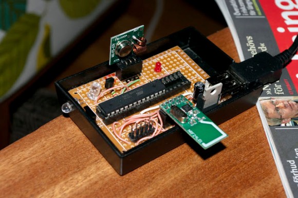
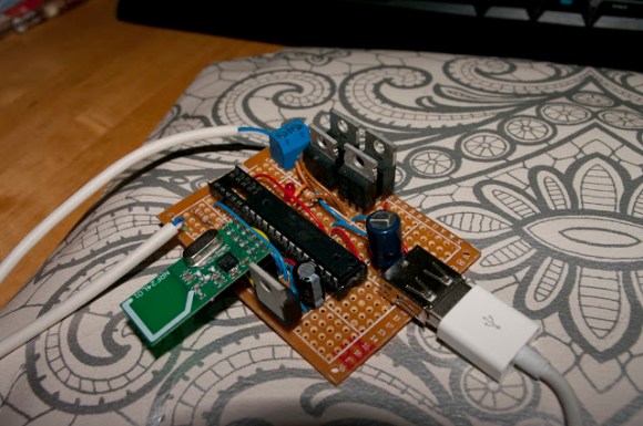
To do this, [Kalle] came up with a wireless temperature controller for his home brewing setup. The device uses a heat exchanger to cool the wort. An ATmega88 connected to a H-bridge controls a valve that regulates flow through the heat exchanger. It reads the current temperature from a LM35 temperature sensor and actuates the valve to bring the wort to a set point.
A neat addition to the build is a wireless radio. The nRF24L01 module provides a wireless link to a computer. There’s an Android application which communicates with the computer, providing monitoring of the temperatures and control over the set point from anywhere [Kalle] can get an internet connection.