BGA Soldering And Inspection

If you want to build cool things these days, you’ve probably had to master surface mount electronics. However, for many people, ball grid array (BGA) is still intimidating. Have a look at [VoltLog’s] video about his techniques for soldering BGA and inspecting that you managed to do it right.

He’s got quite a few tips about things like surface finish and flux selection. It looks easy when he does it. Of course, having a good PCB with good registration markings will help too.

Continue reading “BGA Soldering And Inspection”

Thinking About Creating A Raspberry Pi Replacement?

If you’ve ever wanted to try your hand at creating a Raspberry Pi-like board for yourself, you should check out [Jay Carlson’s] review of 10 different Linux-capable SoCs. Back in the 1960s, a computer was multiple refrigerator-sized boxes with thousands of interconnections and building one from scratch was only a dream for most people. Then ICs came and put all the most important parts in a little relatively inexpensive IC package and homebrew computing became much more accessible. Systems on Chip (SoC) has carried that even further, making it easier than ever to create entire systems, like the Pi and its many competitors.

Only a few years ago, making an SoC was still a big project because the vendors often didn’t want to release documentation to the public. In addition, most of the parts use ball grid array (BGA) packaging. BGA parts can be hard to work with, and require a multilayer PC board. Sure, you can’t plug these into a typical solderless breadboard. But working with these relatively large BGAs isn’t that hard and multilayer boards are now comparatively cheap. [Jay] reports that he got cheap PCBs and used a hot plate to build each board, and has some sage advice on how to do it.

Continue reading “Thinking About Creating A Raspberry Pi Replacement?”

How To Design A BGA Breakout Module

Surface mount devices can take some adjusting to for hackers primarily used to working with through-hole components. Despite this, the lure of the hottest new parts has enticed even the most reticent to learn to work with the technology. Of course, time rolls on and BGA parts bring further difficulties. [Nate] from SparkFun worked on the development of the RedBoard Artemis, and broke down the challenges involved.

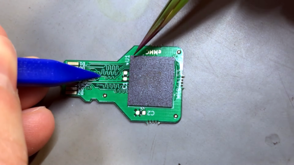
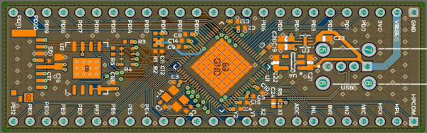
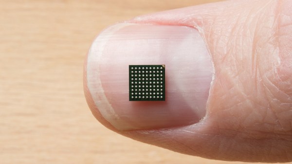
The RedBoard Artemis is an Arduino-compatible devboard built around the Ambiq Apollo3 chip. In addition to packing Bluetooth and 1 MB of Flash, it’s also capable of running TensorFlow models and using tiny amounts of power. The chip comes in an 81-Ball Grid Array at 0.5mm pitch, which meant SparkFun’s usual PCB fabrication methods weren’t going to cut it.

An initial run of prototype boards was run using 4 layers, blind and buried vias, and other fancy tricks to break out all the necessary signals. While this worked well, it was expensive and inefficient. The only part of the board that needed such fabrication was around the chip itself; the rest of the board could be produced with cheaper 2-layer methods. To improve this for mass production, instead, an SMD module was created to house the Apollo3, which could then be dropped into new designs on cheaper boards as necessary.

[Nate] does a great job of explaining the engineering involved, as well as sharing useful tips for others going down a similar path. So far, this is just part 1, with future posts promising to cover the RF shield design and FCC certification process. [Nate] has always been keen to share his wisdom, and we can’t wait to see what comes next!

IR Rework Station

Modern surface mount components often need special tools for rework. However, those tools can be expensive. [Michael Skrepsky] wanted an infrared rework station, but didn’t like the price. So he built his own.

According to [Michael] he used a lot of scrap in the construction. . He used K-type thermocouples, optotriacs, triacs, a 20×4 display and, of course, an Arduino. An old bathroom heater, along with a 600W and 100W halogen bulb work as heaters.

Continue reading “IR Rework Station”

Hand Soldering BGA Parts Should Be A Circus Act

Okay, we think it’s questionable when people say they have no problem soldering QFN packages, but BGA? Granted this chip has far fewer balls on it than many, but it’s still quite impressive that [Xevel] was able to solder this BGA breakout by hand.

The chip you see above is a TMP006 infrared temperature sensor from TI. [Xevel] picked up the part but didn’t want to break the bank when prototyping by buying a proper PCB to host it. There are only eight conductors on it, arranged in a grid with 0.5mm pitch. That didn’t seem to scare him off, as the video after the break shows him connecting each to a conductor on a hunk of stripboard.

[Xevel] mentions that this is a dead-bug style project. Usually you glue the part upside down when using that technique, but it needs line of sight to get an accurate temperature reading so he first cut a hole in the substrate. We’d bet he’s using wire-wrapping wire to make the connections. It’s a very fine solid core wire which is perfect for this kind of work.

Continue reading “Hand Soldering BGA Parts Should Be A Circus Act”

Accessing BGA Pins

[Philip] developed a method of tracking down the pins of a Ball Grid Array. He wanted to do so in order to add USB host functionality to his HP Jordan 720. The method doesn’t directly connect to the BGA but instead finds a via or other access point to serve as a solder point. He first looks up the pin in the BGA datasheet. Once located, he uses the bristle of a toothbrush (teal) to act as a backstop and feeds in some enameled wire (brown) to the appropriate ball. A multimeter is used to check connectivity between the wire and the vias around the chip.

Patience young grasshopper, this should work but it might take a while.