Crystal oscillators are incredibly useful components, but they come with one little snag: their oscillation is temperature-dependent. For many applications the relatively small deviation is not a problem, but especially for precision instruments this is a deal breaker. Enter the oven controlled crystal oscillator, or OCXO. These do basically what it says on the tin, but what’s inside them? [Kerry Wong] took apart a vintage Toyocom TCO-627VC 10 MHz OCXO, revealing a lot more complexity than one might assume.
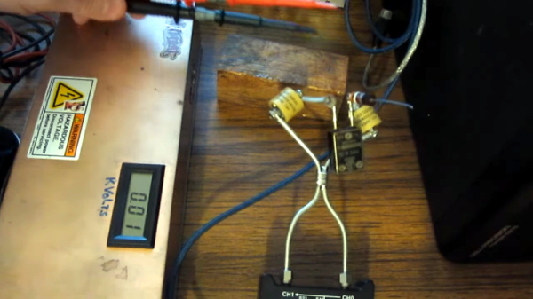
Inside the insulated enclosure there is of course the crystal oscillator itself, which has a heating coil wrapped around it. Of note is that other OCXOs that [Kerry] took apart had more insulation, as well as other ways of providing the thermal energy. In this particular unit a thermistor is attached to the crystal’s metal case to measure its temperature and provide feedback to the heating circuit. The ICs on the PCB are hard to identify due to the conformal coating, but at least one appears to be a 74LS00, alongside a 78L05 voltage regulator which reduces the 12V input voltage.
As an older OCXO it probably is a lot chunkier than newer units, but the basic principle remains the same, with a heating loop that ensures that the crystal inside the unit remains at the same temperature.
Continue reading “Inside A Vintage Oven Controlled Crystal Oscillator”