FLOSS Weekly Episode 779: Errata Prevention Specialist

This week Jonathan Bennett and Dan Lynch sit down with Andy Stewart to talk about Andy’s Ham Radio Linux (AHRL)! It’s the Linux distro designed to give hams the tools they need to work with their radios. What’s it like to run a niche Linux distro? How has Andy managed to keep up with this for over a decade? And what’s the big announcement about the project breaking today?

Continue reading “FLOSS Weekly Episode 779: Errata Prevention Specialist”

Emails Over Radio

The modern cellular network is a marvel of technological advancement that we often take for granted now. With 5G service it’s easy to do plenty of things on-the-go that would have been difficult or impossible even with a broadband connection to a home computer two decades ago. But it’s still reliant on being close to cell towers, which isn’t true for all locations. If you’re traveling off-grid and want to communicate with others, this guide to using Winlink can help you send emails using a ham radio.

While there are a number of ways to access the Winlink email service, this guide looks at a compact, low-power setup using a simple VHF/UHF handheld FM radio with a small sound card called a Digirig. The Digirig acts as a modem for the radio, allowing it to listen to digital signals and pass them to the computer to decode. It can also activate the transmitter on the radio and send the data from the computer out over the airwaves. When an email is posted to the Winlink outbox, the software will automatically send it out to any stations in the area set up as a gateway to the email service.

Like the cellular network, the does rely on having an infrastructure of receiving stations that can send the emails out to the Winlink service on the Internet; since VHF and UHF are much more limited in range than HF this specific setup could be a bit limiting unless there are other ham radio operators within a few miles. This guide also uses VARA, a proprietary protocol, whereas the HF bands have an open source protocol called ARDOP that can be used instead. This isn’t the only thing these Digirig modules can be used for in VHF/UHF, though. They can also be used for other digital modes like JS8Call, FT8, and APRS.

Continue reading “Emails Over Radio”

Understand Your Tools: Finger Exercises

A dip meter is basically a coil of wire that, when you excite it, you can use to tell if something inside that coil is resonating along. This lets you measure unknown radio circuits to figure out their resonant frequency, for instance. This week, we featured a clever way to make a dip meter with a nanoVNA, which is an odd hack simply because a dip meter used to be a common spare-parts DIY device, while a vector network analyzer used to cost more than a house.

Times have changed, and for the better. Nowadays, any radio amateur can pick up a VNA for less than the cost of all but the cheesiest of walkie talkies, putting formerly exotic test equipment in the hands of untrained mortals. But what good is a fancy-pants tool if you don’t know how to use it? Our own Jenny List faced exactly this problem when she picked up a nanoVNA, and her first steps are worth following along with if you find yourself in her shoes.

All of this reminded me of an excellent series by Mike Szczys, “Scope Noob”, where he chronicled his forays into learning how to use an oscilloscope by running all of the basic functions by working through a bunch of test measurements that he already knew the answer to.

It strikes me that we could use something like this for nearly every piece of measuring equipment. Something more than just an instruction manual that walks you through what all the dials do. Something that takes you through a bunch of example projects and shows you how to use the tool in question through a handful of projects. Because these days, access to many formerly exotic pieces of measuring gear has enabled many folks to have gear they never would have had before – and all that’s missing is knowing how to drive them.

How Much Bandwidth Does CW Really Occupy?

Amateur radio license exams typically have a question about the bandwidths taken up by various modulation types. The concept behind the question is pretty obvious — as guardians of the spectrum, operators really should know how much space each emission type occupies. As a result, the budding ham is left knowing that continuous wave (CW) signals take up a mere 150 Hertz of precious bandwidth.

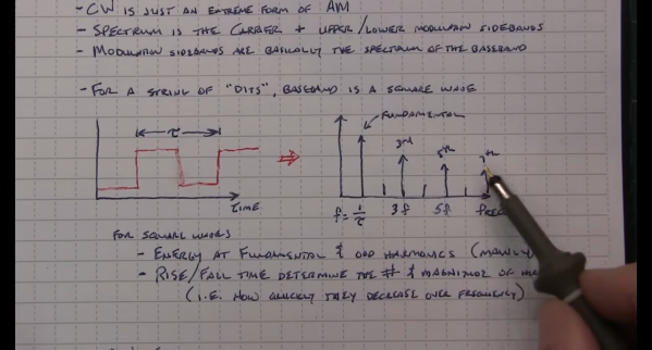
But is that really the case? And what does the bandwidth of a CW signal even mean, anyway? To understand that, we turn to [Alan (W2AEW)] and his in-depth look at CW bandwidth. But first, one needs to see that CW signals are a bit special. To send Morse code, the transmitter is not generating a tone for the dits and dahs and modulating a carrier wave, rather, the “naked” carrier is just being turned on and off by the operator using the transmitter’s keyer. The audio tone you hear results from mixing the carrier wave with the output of a separate oscillator in the receiver to create a beat frequency in the audio range.

That seems to suggest that CW signals occupy zero bandwidth since no information is modulated onto the carrier. But as [Alan] explains, the action of keying the transmitter imposes a low-frequency square wave on the carrier, so the occupied bandwidth of the signal depends on how fast the operator is sending, as well as the RF rise and fall time. His demonstration starts with a signal generator modulating a 14 MHz RF signal with a simple square wave at a 50% duty cycle. By controlling the keying frequency, he mimics different code speeds from 15 to 40 words per minute, and his fancy scope measures the occupied bandwidth at each speed. He’s also able to change the rise and fall time of the square wave, which turns out to have a huge effect on bandwidth; the faster the rise-fall, the larger the bandwidth.

It’s a surprising result given the stock “150 Hertz” answer on the license exam; in fact, none of the scenarios [Allen] tested came close to that canonical figure. It’s another great example of the subtle but important details of radio that [Alan] specializes in explaining.

Continue reading “How Much Bandwidth Does CW Really Occupy?”

Decoding JS1YMG: First Ham Radio Station On The Moon After SLIM Mission

When Japan’s SLIM lunar lander made a rather unconventional touch-down on the lunar surface, it had already disgorged two small lunar excursion vehicles from its innards: LEV-1 and LEV-2. Of these, the LEV-1 is not only capable of direct to Earth transmission, but it also has been assigned its own amateur radio license: JS1YMG, which makes it the first Ham radio station on the Moon. LEV-1 receives data from LEV-2, which is transmitted to Earth using its 1 Watt UHF circular polarization antenna as Morse code at 437.410 MHz. Although the data format hasn’t been published, [Daniel Estévez] (EA4GPZ) has been sleuthing around to figure it out.

Using captures from the 25 meter radiotelescope at Dwingeloo in the Netherlands, [Daniel] set to work deciphering what he knew to be telemetry data following a CCSDS standard. After some mix-and-matching he found that the encoding matched PCM/PSK/PM with a symbol rate of 64 baud and 2048 kHz subcarrier. The residual carrier is modulated in amplitude with Morse code, but initially this Morse code made no sense.

Continue reading “Decoding JS1YMG: First Ham Radio Station On The Moon After SLIM Mission”

Directional Antenna Stands Tall

When you think of directional ham radio antennas, you probably think of a Yagi, cubical quad, or a log-periodic antenna. These antennas usually are in a horizontal configuration up on a high tower. However, it is possible to build beams with a vertical orientation and, for some lower frequencies, it is far more practical than mounting the elements on a boom. [DXCommander] shows us his 40 meter two-element vertical antenna build in the video below.

A typical Yagi is just a dipole with some slightly longer or shorter elements to direct or reflect the signal. A normal vertical, however, is nothing more than half of a dipole that uses the ground as the other half. So it is possible to create reflectors and directors with a vertical-driven element.

Continue reading “Directional Antenna Stands Tall”

Pico-WSPR-tx Does It In Software

What do you need to make a radio transmitter? There are builds that work with just a couple of transistors. But how about a GPS-disciplined small signal beacon? You can actually get the job done for less than the cost of a fancy hamburger, thanks to [RPiks]’s pico-WSPR-tx and the Weak Signal Propagation Reporter Network (WSPR).

WSPR is a digital protocol where a beacon encodes its callsign, location, and transmitting power, and then sends it out to a network of receiving stations worldwide. The idea is to use the data coming from the beacons to determine whether radio propagation conditions are good or not; if you hear a quiet signal from afar, they’re good in that direction. [RPiks]’s beacon design simply includes a Raspberry Pi Pico and a GPS receiver. Everything else is software.

Of course, this means that it’s using the Pico’s GPIO pins for transmission. Maybe you want to add some filtering to take off the rough square-wave edges, and/or maybe you want to boost the power a little bit with an external amplifier. If so, check out our own $50 Ham column’s advice on the topic. But you don’t need to. Just a Pico and a GPS should get you working, if you want to test the WSPR waters.