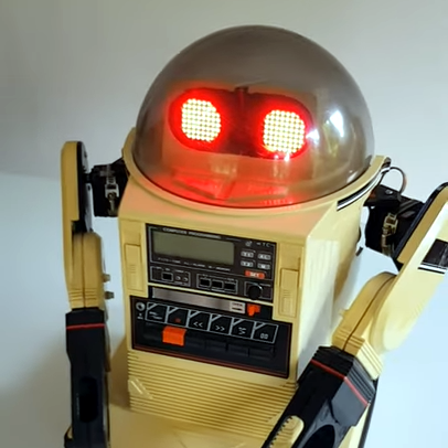
[Ramin assadollahi] has been busy rebuilding and improving an Omnibot 5402, and the last piece of hardware he wanted to upgrade was some LED matrix eyes and a high quality Raspberry Pi camera for computer vision. An Omnibot was something most technical-minded youngsters remember drooling over in the 80s, and when [ramin] bought a couple of used units online, he went straight to the workbench to give the vintage machines some upgrades. After all, the Omnibot 5402 was pretty remarkable for its time, but is capable of much more with some modern hardware. One area that needed improvement was the eyes.
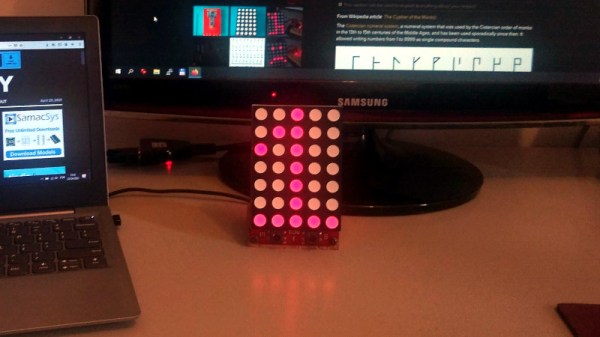
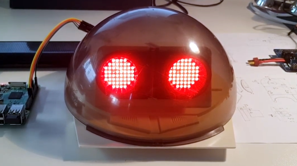
The eyes on the original Omnibot could light up, but that’s about all they were capable of. The first upgrade was installing two 8×8 LED matrix displays to form what [ramin] calls Minimal Expressive Eyes (MEE), powered by a Raspberry Pi. With the help of a 3D-printed adapter and some clever layout, the LED matrix displays fit behind the eye plate, maintaining the original look while opening loads of new output possibilities.
Adding a high quality Raspberry Pi camera with wide-angle lens was a bit more challenging and required and extra long camera ribbon connector, but with the lens nestled just below the eyes, the camera has a good view and isn’t particularly noticeable when the eyes are lit up. Having already upgraded the rest of the hardware, all that remains now is software work and we can’t wait to see the results.
Two short videos of the hardware are embedded below, be sure to give them a peek. And when you’re ready for more 80s-robot-upgrading-action, check out the Hero Jr.
Continue reading “Omnibot From The 80s Gets LED Matrix Eyes, Camera” →