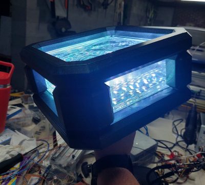
[Nick Lombardy] took on a job almost every maker imagines themselves doing at some point. He built a giant LED wall and he did a damn fine job of it, too. Introducing BoneBlocker.
BoneBlocker is an 8 x 14 wall of glass blocks that lives at a bar called The Boneyard. Each block was given a length of WS2812B LED strip. 30 LED/meter strips were chosen, as initial maths on the 60 LED/meter strips indicated the whole wall would end up drawing 1.5 kW. Discretion, and all that.
The whole display is run from a WT32-ETH01 board, which is a fast ESP32-based module that has onboard Ethernet to boot. [Nick] used the WLED library as he’d seen others doing great things with it, performance-wise. He ended up using one board per column to keep things fast, but he reckons this was also probably a little bit of overkill.
His article steps through the construction of the wall, the electronics, and the software required to get some games working on the display. The final result is quite something. Perhaps the best bit is his explanation of the custom controller he built for the game. Dig into it, you won’t be disappointed.
In particular, we love how the glass blocks elevate this display to a higher aesthetic level. We’ve seen other great projects tread this same route, too. Video after the break.

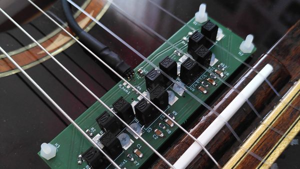
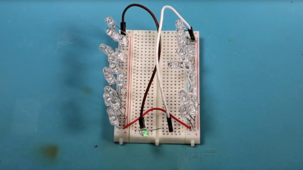
 The concept is simple. You place an LED and a phototransistor in a U-shaped channel, and place it so that the string runs through it. You repeat this for each string. Thus, as a string vibrates, it interrupts the light travelling from the LED to the phototransistor. This generates a voltage that varies with the frequency of the string’s vibration. Funnily enough, this type of pickup will work just fine on both nylon and steel strings, if you were so inclined to try it.