Dreaming Of A Transparent (PCB) Christmas

[Carl] wanted to put his force sensors on a transparent PCB and had to ask his board vendor for a special sample. Flexible PCBs are available on transparent substrates made of PET, but they are not as common as polyimide boards. As [Carl] found out, these boards are a bit thicker, a bit less flexible, and don’t hold up to very high heat as well as the standard boards. Undeterred, he designed a 3D Christmas tree using the clear boards. The result that you can see in the video below looks pretty good and would have been hard to duplicate with conventional means.

When you build the board it is as a flat spiral, but lifting it in the center allows it to expand into a conical tree shape. The circuit itself is just an LED blinker, but the flexible board is the interesting part.

Continue reading “Dreaming Of A Transparent (PCB) Christmas”

Avoiding PCB Crosstalk

Now that it is relatively cheap and easy to create a PCB, it is a common occurrence for them to be used in projects. However, there are a lot of subtleties to creating high-performance boards that don’t show up so much on your 555 LED blinker. [Robert Feranec] is well-versed in board layout and he recently highlighted an animation on signal crosstalk with [Eric Bogatin] from Teledyne LeCroy. If you want a good understanding of crosstalk and how to combat it, you’ll want to see [Eric’s] presentation in the video below.

Simplifying matters, the heart of the problem lies in running traces close together so that the magnetic fields from one intersect the other. The math is hairy, but [Eric] talks about simple ways to model the system which may not be exact, but will be close enough for practical designs.

Continue reading “Avoiding PCB Crosstalk”

Oscilloscope And Microscope Augmented With Ghosts

Augmented reality saw a huge boom a few years ago, where an image of the real world has some virtual element layer displayed on top of it. To get this effect to work, however, you don’t need a suite of software and smart devices. [elad] was able to augment a microscope with the output from an oscilloscope, allowing him to see waveforms while working on small printed circuit boards with the microscope.

The build relies on a simplified version of the Pepper’s Ghost illusion. This works by separating two images with a semi-transparent material such as glass, placed at an angle. When looking through the material, the two images appear to blend together. [elad] was able to build a box that attaches to the microscope with a projection of the oscilloscope image augmented on the view of the microscope.

This looks like it would be incredibly useful for PCBs, especially when dealing with small SMD components. The project is split across two entries, the second of which is here. In one demonstration the oscilloscope image is replaced with a visual of a computer monitor, so it could be used for a lot more applications than just the oscilloscope, too. There aren’t a lot of details on the project page though, but with an understanding of Pepper’s Ghost this should be easily repeatable. If you need more examples, there are plenty of other builds that use this technique.

Continue reading “Oscilloscope And Microscope Augmented With Ghosts”

Drill Thrice, Solder Once

If you design printed circuit boards, then you will have also redesigned printed circuit boards. Nobody gets it right the first time, every time. Sometimes you can solder a scrap of 30gauge wire, flip a component 180°, or make a TO-92 transistor do that little pirouette thing where the legs go every-which-way. If you angered the PCB deities, you may have to access a component pad far from an edge. [Nathan Seidle], the founder of Sparkfun, finds himself in this situation, but all hope is not lost.

Our first thought is to desolder everything, then take a hot iron and tiny wires to each pad. Of course, this opens up a lot of potential for damage to the chip, cold joints, and radio interference. Accessing the pin in vivo has risks, but they are calculated. The idea is to locate the pin, then systematically drill from the backside and expose the copper. [Nate] also discovers that alcohol will make the PCB transparent so you can peer at the underside to confirm you have found your mark.

In a real, “fight fire with fire” idea, you can rework with flex PCBs or push your PCB Fu to the next level and use PCBs as your enclosure.

Hackaday Superconference: Nick Poole On Boggling The Boardhouse

By now we are all used to the role of the printed circuit board in artwork, because of the burgeoning creativity in the conference and unofficial #BadgeLife electronic badge scenes. When the masters of electronic design tools turn their hand to producing for aesthetic rather than technical reasons, the results were always going to be something rather special.

Nick Poole is an ace wrangler of electrons working for SparkFun, and as such is someone with an impressive pedigree when it comes to PCB design. Coming on stage sporting a beret with an awesome cap badge, his talk at the recent Hackaday Superconference concerned his experience in pushing the boundaries of what is possible in PCB manufacture. It was a primer in the techniques required to create special work in the medium of printed circuit boards, and it should be essential viewing for anybody with an interest in this field.

Though he starts with the basics of importing graphics into a PCB design package, the meat of his talk lies in going beyond the mere two dimensions of a single PCB into the third dimension either by creating PCBs that interlock, or by stacking boards.

Continue reading “Hackaday Superconference: Nick Poole On Boggling The Boardhouse”

A Complete Desktop PCB Etching Station

Right now you can get a custom circuit board delivered to your door in about a week for just a few dollars. There’s little reason to make your own circuit boards at home anymore, but when you need a board now, you want to have that capability. [Tuval Ben Dosa] designed a complete PCB etching station that is the perfect tool for making printed circuit boards at home. It’s got everything you need for the perfect etch, and with this setup you can make a board in hours instead of waiting for days.

The chemistry for any etching setup is important, and in recent years the entire community has moved from ferric chloride to copper chloride for a very good reason: you can recharge copper chloride etchant by bubbling oxygen (or air) through it, whereas ferric chloride is a one-use etchant.

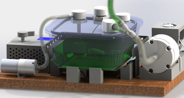
The mechanical part of this build consists of an airtight glass food container sitting on top of a PCB heating element not unlike the heated bed of a 3D printer. Along with that is an I2C temperature sensor encased in a silicone tube, a stir bar, diaphram pump, and a few pumps to blow air into the etchant and pump out the chlorine gas generated. This is controlled by a small microcontroller with a UI consisting of just an encoder and OLED display.

If you’re looking for builds that will etch copper and brass at home, this has been something that has been done before. The Etchinator is a fantastic build capable of making everything from printmaking plates to printed circuit boards. That’s a build that requires a lot of work, and this small, compact etching station does everything you need without taking up too much space in the shop. Check out the video below.

Continue reading “A Complete Desktop PCB Etching Station”

What’s The Deal With Square Traces On PCBs

When designing a printed circuit board, there are certain rules. You should place decoupling capacitors near the power pins to each chip. Your ground planes should be one gigantic fill of copper; two ground planes connected by a single trace is better known as an antenna. Analog sections should be kept separate from digital sections, and if you’re dealing with high voltage, that section needs to be isolated.

One that I hear a lot is that you must never put a 90-degree angle on a trace. Some fear the mere sight of a 90-degree angle on a PCB tells everyone you don’t know what you’re doing. But is there is really no greater sin than a 90-degree trace on a circuit board?

This conventional wisdom of eschewing 90-degree traces is baked into everything we know about circuit board design. It is the first thing you’re taught, and it’s the first thing you’ll criticize when you find a board with 90-degree traces. Do square traces actually matter? The short answer is no, but there’s still a reason we don’t do it.

Continue reading “What’s The Deal With Square Traces On PCBs”