Like many of us, [quincy] feels the distracting pull of non-work programs on what has become a mixed-use computer. So what’s the answer to the puzzle of work-life balance? We’re not sure, but time management and keeping track of tasks will probably get you most of the way there. The only problem is that keeping track of these things is boring and tedious and way too easy to forget, even for the fun tasks.
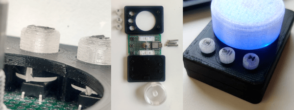
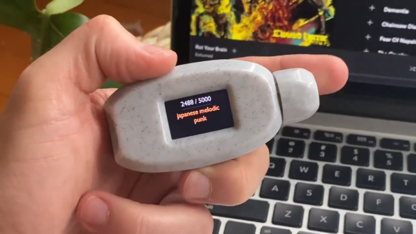
Similar commercial gadgets exist to serve this time-tracking purpose, but [quincy] wanted something much cooler that would work the same way: turn the indicator to the current task, and the status gets recorded on a computer. Rather than some smart polygon with informative stickers on each face à la the Timeflip2, [quincy] built a rotary task manager that serves the same purpose, but does it with magnets.
Our favorite part aside from the magnets has to be the clever binary encoding work. [quincy] is using three photoresistors and a single green LED to create a 3D-printed gray encoder that sidesteps the need to ever flip two bits at once. An Arduino takes care of reading the 3-bit code and converting it back into a decimal. There are more updates to come, including the main .ino file, but you can start printing the pieces while you wait.
If you have trouble staying on task, maybe you need a Pomodoro timer. We’ve seen a few over the years, ranging from the minimal to the sculptural.
![]()